
In the Question Line Video below, Jason answers a student’s question regarding whether a feature of size can be designed to both Maximum Material Condition (MMC) and Least Material Condition (LMC) boundary constraints.
A student recently submitted the following question to our Question Line: “Is it possible or common for a feature of size to be constrained to the boundaries of both the MMC and the LMC? It seems that if a high level of precision is required, one may not want the form of the part to cross either of these boundaries.”
First, a quick review. Every feature of size has two size boundaries – the Maximum Material Condition (MMC) and the Least Material Condition (LMC). The Maximum Material Condition is the state in which the maximum amount of material exists within its dimensional tolerance. The Least Material Condition state is the opposite – it is the state in which the least amount of material exists within its dimensional tolerance.
Our student wanted to know if a feature can be constrained to both MMC and LMC boundaries. This question is referring to Rule #1 of GD&T, the envelope principle. Rule #1 states that the form of a feature of size is controlled by its limits of size (size tolerances), meaning that the surface of any regular feature of size cannot extend beyond the envelope of perfect form at MMC. So why do we design to MMC envelope boundaries? And is it possible to design to both MMC and LMC?
Let’s look at some examples to answer these questions. In Figure 1, we have a block with a hole in it. This hole’s size tolerances give us a MMC for the hole of 1.247, and a LMC for the hole of 1.253. Looking to Rule #1, we understand that the form of this hole is restricted to the MMC envelope. This means that the hole can have form error only if it remains contained within the envelope. So, if the size of the hole itself is measured at 1.247, there is no room for any form error. If the size of the hole is equal to the LMC, 1.253, you can have up to .006 of form error and still pass inspection.
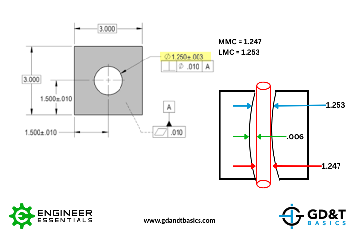
Figure 1: MMC Boundary Envelope for an Internal Feature of Size
The reason we design to an MMC boundary envelope is to ensure assembly. Assume that we are manufacturing a pin to fit within the hole in the part above. The stack up of the size and the form of the pin cannot be larger than this hole, else it will not assemble. Therefore, we would design the mating pin to the same MMC envelope as the hole. By doing this, we ensure that the largest allowable pin size + form will fit within the smallest hole size + form.
Conversely, it should be noted that if the LMC modifier is applied to a feature control frame, then Rule #1 flips. It now would state that the feature cannot deviate beyond an envelope of perfect form at LMC. This means the largest hole size + form when stacked up cannot deviate beyond an envelope of perfect form at the LMC size. This scenario no longer ensures assembly of a mating feature. However, this does guarantee control of a minimum wall thickness adjacent to the hole. An example of this scenario is shown below in Figure 2.
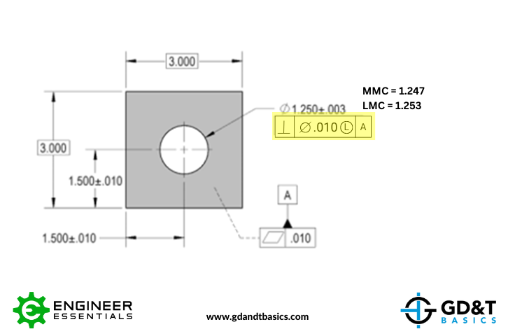
Figure 2: LMC Boundary Envelope Used to Control Minimum Wall Thickness
Note – whether we are controlling size and form with respect to LMC or MMC envelopes, the opposite side of the tolerance is still being restricted by the local sizes (i.e., any 2-point measurement). If the functional intent of the feature requires assembly as well as being concerned with wall thicknesses, there are calculations involving virtual and resultant conditions that can ensure we have our bases covered. Regardless, you are ONLY constraining the form of a feature to one boundary envelope, MMC or LMC, not both.
Summary
Rule #1 of Geometric Dimensioning and Tolerancing states that the form of a feature of size is controlled by its limits of size. Typically, it is the MMC size limit that is creating this boundary envelope, as designing to the MMC boundary constraints will ensure assembly of mating parts. When the LMC modifier is used, Rule #1 requires perfect form at the LMC of the feature. This guarantees that no matter the size or form of the feature, we know the two will not reduce the wall thickness beyond a pre-designed value. Designing to LMC boundary constraints is less common, and only done when you are concerned with controlling minimum wall thickness, not assembly. Moreover, you will only design a feature to either MMC or LMC boundary constrains, not both.
Jason walks through these examples and more in the video above. Check it out for more information.
The one-page GD&T reference that you will use every day
A visual breakdown of every core GD&T symbol and what it controls, all on one page. Bookmark it. Print it. Actually use it.
Download the Chart