

The position symbol is one of the most useful symbols in GD&T because it creates a diametric tolerance zone that more closely aligns with the functional intent of a feature. But did you realize that you can use the position control to allow more tolerance in one direction and less in another? In the video below, Jason explains how to achieve bidirectional position control through the use of a Multiple Single Segment Feature Control Frame.
Coordinate Dimensions to GD&T Position
In the figure below, we have an aluminum part with two thru holes, in which fasteners will pass through and then thread into the tapped holes in the red part below it. To have a functional part, the spacing between the holes and the spacing to the edge of the part must be maintained and have appropriate tolerances. We have a coordinate dimensioned drawing for this aluminum part, and will convert it to use GD&T Position to gain the benefits of round tolerance zones.
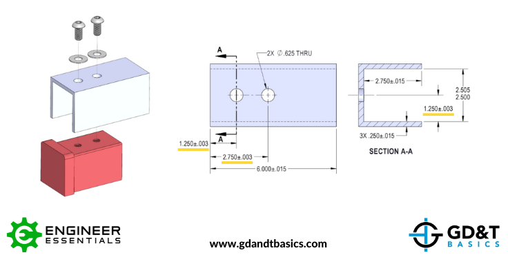
Figure 1: Aluminum Part Drawing with Coordinate Dimensions
The coordinate dimensioned drawing gives a +/- .003 tolerance for the location of the holes in both X and Y dimensions, resulting in a square tolerance zone. To use the GD&T Position control, we will convert the allowable X and Y deviation into an equivalent diametric deviation using the Pythagorean theorem (A2+B2=C2). This calculation results in a radial deviation of .004, which we will multiply by 2 to get the diametric deviation – the allowable Position Tolerance of .008. (Alternatively, if you don’t want to do the math, you can use our handy Position Calculator!)
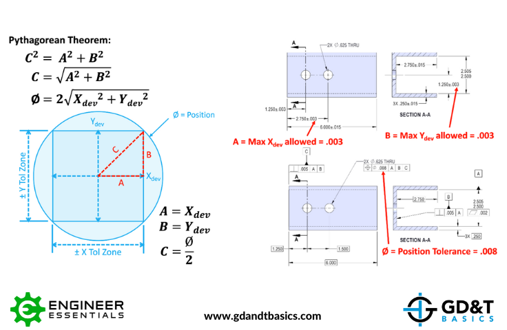
Figure 2: Converting Coordinate Tolerances into Diametric Position Tolerance
We have converted the aluminum part drawing to the GD&T drawing in Figure 3, below. This drawing now has datum features identified, includes basic dimensions for the location of the holes, and includes a feature control frame (FCF) with Position controlling the location tolerance of the holes.
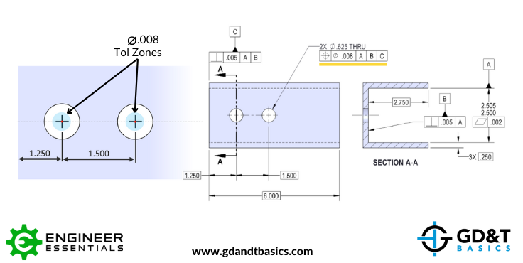
Figure 3: Aluminum Part with GD&T Position Control
In Figure 3, we have illustrated the .008 diameter tolerance zones for the location of the two thru holes. You can see that the tolerance zones are centered at true position (the basic dimensions of 1.250 and 1.500 on the drawing). These holes can deviate in any direction as long as their axes stay inside the tolerance zones. If each hole were to deviate the max distance in opposite directions, the maximum distance between their centers would be 1.508.
Bidirectional Position Control
But what if the design intent was for bidirectional position control – for the pattern of holes to be able to shift quite a bit in the X direction while still maintaining the tighter tolerance in between holes and in the Y direction? How can we do this using GD&T Position?
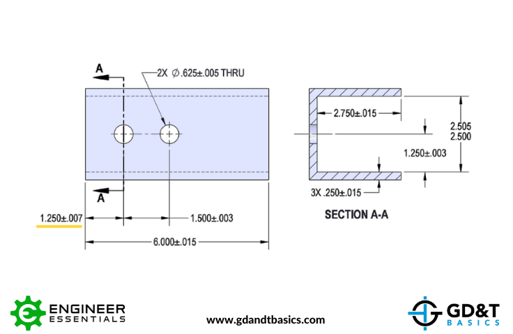
Figure 4: Coordinate Drawing with Larger Tolerance
In the coordinate drawing in Figure 4, we see that there is a larger tolerance locating the first hole of the pattern (+/-.007), but we have the original .003 tolerance for the distance between the holes and in the Y direction to ensure that the holes can align with the tapped holes in the red block below it. Our GD&T drawing must be modified to allow for a larger position tolerance of the pattern while keeping the tighter tolerance for placement of the holes relative to each other. This is done by using a Multiple Single Segment (MSS) Feature Control Frame.
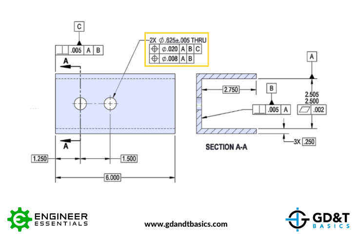
Figure 5: GD&T Drawing with Multiple Single Segment Feature Control Frame
A Multiple Single Segment Feature Control Frame is essentially two stacked feature control frames. In Figure 5, we see that the top FCF has a position tolerance of .020 with respect to Datums A, B, and C. By referencing these three datums, all 6 degrees of freedom are constrained and the .020 diameter tolerance zones are locked at true position. Looking only at the top FCF, the axes of the holes must be within the .020 tolerance zones, which allows both holes to deviate quite a bit more in both the X & Y directions than in the original example. This satisfies the looser tolerance for the placement of the hole pattern in the X direction, but does not meet the tighter requirement for the position of the holes vertically as well as with respect to each other.
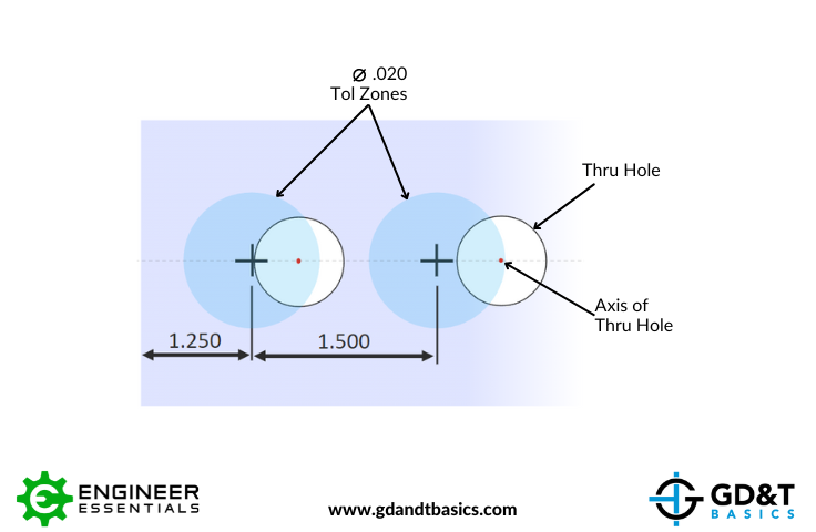
Figure 6: Larger Tolerance Zone of Top FCF of the Multiple Single Segment FCF
We further refine the position tolerance zone by adding a second FCF, thus creating the Multiple Single Segment FCF. This second FCF will have the original .008 tolerance zone, but will reference only Datums A and B. By referencing these two datums, we are controlling the Y position of the smaller tolerance zones, but not the X position. This allows the .008 tolerance zones to move laterally, and because these holes are being controlled as a pattern, the smaller tolerance zones must maintain the 1.500 distance between them. This again results in a maximum distance between holes of 1.508. In order to pass both specifications of the Multiple Single Segment FCF, the axes of the holes must simultaneously be within the .020 and the .008 tolerance zones.
Figure 7: Multiple Single Segment Tolerance Zone
In summary, a Multiple Single Segment FCF can be utilized to achieve bidirectional position control. The top feature control frame controls a looser tolerance zone that allows a large amount of shift in all directions, and the bottom feature control frame refines the position to a smaller tolerance zone but only refines one direction of location. Thus, resulting in a combined effect of a “slotted” tolerance zone when overlapped. This allows us to use GD&T Position to allow more tolerance in one direction and less in another on a pattern of holes, achieving bidirectional position control.
(For additional information regarding Multiple Single Segment Feature Control Frames and an explanation of how they compare to Composite Control Frames, check out this article: Composite Position vs Multiple Single Segment Tolerances.)
The one-page GD&T reference that you will use every day
A visual breakdown of every core GD&T symbol and what it controls, all on one page. Bookmark it. Print it. Actually use it.
Download the Chart