

In our question line videos, our GD&T instructors answer common questions submitted by our students. Today’s video answers the question, “Can you use the MMC modifier and still ensure a minimum wall thickness?”
To answer this question, we are going to look at a drawing of a flywheel and compare how using the MMC modifier or the LMC modifier affects the minimum wall thickness.
Wall Thickness when using the LMC Modifier
The flywheel below includes eight equally spaced holes for the purpose of weight reduction. These holes are not assembly features. In this first example, the Least Material Condition modifier (LMC) is indicated in the feature control frame for the holes. This feature control frame tells us that the holes have a diametric position tolerance of .010 when they measure at LMC with respect to datums A & B.
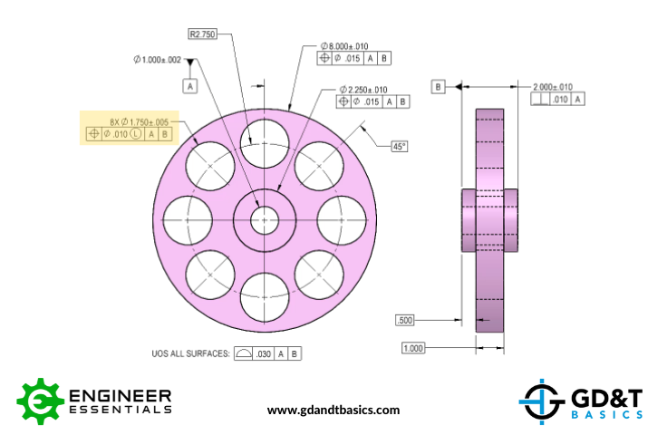
Figure 1: Flywheel drawing with LMC modifier callout
Regardless of whether MMC or LMC is called out on the drawing, every feature of size has two limits defined by its size tolerances. The Maximum Material Condition (MMC) is the condition where the maximum amount of material exists within the feature’s dimensional tolerance. The Least Material Condition (LMC) is where the least amount of material exists within the feature’s dimensional tolerance. For an internal feature, the most material exists when the hole is the smallest size. In this flywheel drawing, the MMC of the hole is equal to 1.745, and the LMC is 1.755.
When LMC or MMC modifiers are called out, we get bonus tolerance as our hole size deviates from the modifier. For LMC, this means that when our hole size decreases, we gain positional tolerance. In our example, when the hole measures at LMC (1.755), we get a .01 position tolerance (.005 radial drift). This sets up the minimum wall thickness. If the diameter of the hole measures at MMC, we get an additional .01 bonus diametric position tolerance. This allows us deviate in position even more, but still maintain the minimum wall thickness. Figure 2 below shows that the minimum wall thickness is maintained when calling out the LMC modifier.
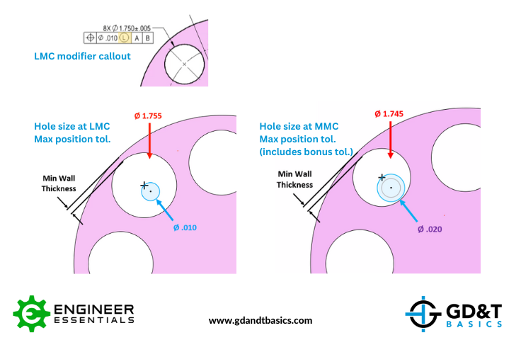
Figure 2: Minimum Wall Thickness held with LMC Modifier Callout
Wall Thickness when using the MMC Modifier
Let’s replace the LMC modifier in the feature control frame with the Maximum Material Condition (MMC) modifier. The feature control frame now instructs us that the hole has a diametric position tolerance of .01 when the hole measures at MMC with respect to datums A & B. When our hole measures at MMC (1.745) we get .01 diametric position tolerance. When the hole measures at LMC (1.755), we have deviated from MMC by .01, so we get an additional .01 diametric position bonus tolerance. Figure 3 below shows that the minimum wall thickness is not maintained when using the MMC modifier.
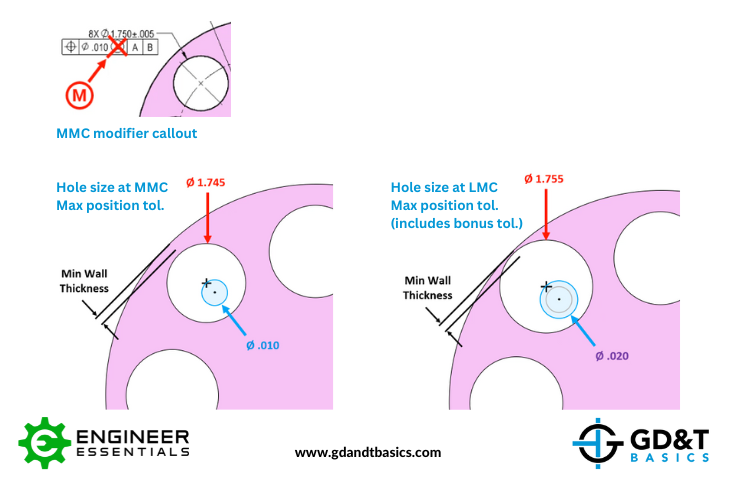
Figure 3: Minimum Wall Thickness Not Ensured with MMC Callout
Summary
We see from our two examples that minimum wall thickness is not ensured when using the MMC modifier. The MMC modifier is not meant for use in this purpose. It is meant for use with assembly features, to ensure that there is not interference between assembled parts.
To ensure a minimum wall thickness, the LMC modifier should be called out.
The one-page GD&T reference that you will use every day
A visual breakdown of every core GD&T symbol and what it controls, all on one page. Bookmark it. Print it. Actually use it.
Download the Chart