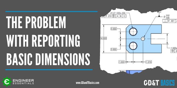
Avoiding Tolerance Stacks with GD&T
Tolerance stacks can be a nightmare. However, when using GD&T rather than coordinate dimensioning, tolerance stack-ups within a part can be avoided.
In Geometric Dimensioning and Tolerancing, Basic Dimensions are theoretically exact dimensions that define the ideal exact location and orientation of surfaces and features of size. A basic dimension is shown on a drawing as a...
What is a Datum Reference Frame? Datums are used in Geometric Dimensioning and Tolerancing drawings to create a reference system for inspecting a manufactured part. This reference system is called a Datum Reference Frame (DRF)....
Having a good understanding of Geometric Dimensioning and Tolerancing is very important for anyone working in a mechanical field. GD&T is the language used in design, manufacturing, and quality inspection to communicate on engineering prints....
Making the decision to invest in GD&T training isn’t always easy. And even once you’ve made that call, you still need to pick a program that’ll teach your team what they need to know. While the concepts...
Today, I’m the President of Engineer Essentials, a company I founded to help engineers, machinists, inspectors, students and others learn the concepts of geometric dimensioning and tolerancing (GD&T). I’m a mechanical engineer and a Certified...
The most common way to produce an internal thread is to drill a hole and then use a tap to produce the thread. This is usually referred to as a tapping drill for the size...
GD&T Basics has partnered with Mitutoyo to demonstrate how to set up and inspect a part using a CMM. In this video, we examine a part designed as a training aid by Mitutoyo, inspecting it...
Geometric dimensioning and tolerancing (GD&T) is a system in manufacturing that can be traced back to the 1940s. It was developed by Stanley Parker while he worked at Royal Torpedo Factory in Alexandria, West Dunbartonshire,...
This 3-part series is great for designers or anyone who may be applying things to an engineering drawing. In this series, we’ll review the top 3 things that manufacturing and quality departments wish you knew...
To determine when to use Profile of a Surface or Coordinate Dimensioning, let’s first look at what the 2009 ASME Y14.5 Geometric Dimensioning and Tolerancing Standard tells us. Paragraph 2.1.1 was revised to emphasize/encourage the...
How are tolerance limits defined? The previous articles in our Intro to Tolerances series have answered the questions, “What is a tolerance?” and “Why use tolerances?” This third and final article in the series explores...
Why use tolerances? In our previous article, “What is a Tolerance?” we introduced the concept of manufacturing tolerances and why they are necessary. In this article, we are going to focus on the benefits of...
What is a tolerance? If you take a look at an engineering drawing, you will notice that there are always limits, or tolerances, placed on a dimension. Why does the designer do this? When a...
What is the difference between the ISO and ASME GD&T standards? Read on to find the answers to these questions and more – and see our GD&T Standards Comparison Chart available to download for free below....
The ASME 2018 Y14.5 GD&T Standard contains a few significant changes, including the elimination of the concentricity constraint. Check out this video article for more on this change!
Properly defining, qualifying, and referencing datum features is essential to ensure that parts are properly manufactured and inspected. To begin exploring proper use of datum features, it is helpful if we first review definitions and...
There can be a lot of confusion when dealing with circularity – especially when identifying the tolerance zone compared to how Rule #1 of Geometric Dimensioning and Tolerancing controls it. In this video, we provide...