Unilateral Tolerance and Bilateral Tolerance
by Seth Elder on October 12, 2020.
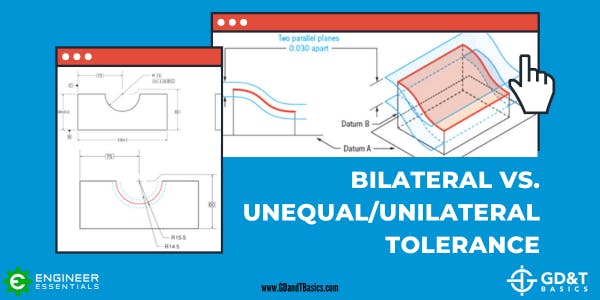
In this article, we explain the differences between bilateral, unilateral, and unequally disposed tolerances. What is a Tolerance? Tolerances on technical drawings communicate the amount of variation permitted from a target dimension. The allowable variation...