

In this video, Tom explains how datums work, together with a datum reference frame, to allow you to inspect an imperfect part.
Datum Fundamentals
A manufactured part will never be perfect. When inspecting a manufactured part, the inspector must compare the imperfect part with the theoretically perfect version shown on the drawing. This can only be done by creating a “perfect grid” to measure the manufactured part against. This “perfect grid” is the datum reference frame.
A datum is a theoretical exact plane, axis, line, point of combination thereof that Geometric Dimensioning and Tolerancing or dimensional tolerances are referenced to. It only exists theoretically, but can be simulated by measurement equipment such as granite slabs, gauge blocks, gauge pins, etc. A datum feature is a tangible surface (planar or cylindrical) on a part where the theoretical datum is constructed. It is usually an important functional surface that other dimensions reference to. A datum and a datum feature are not the same thing because a part is never completely perfect.
A datum reference frame is the coordinate system created by the datums specified in the part drawing.
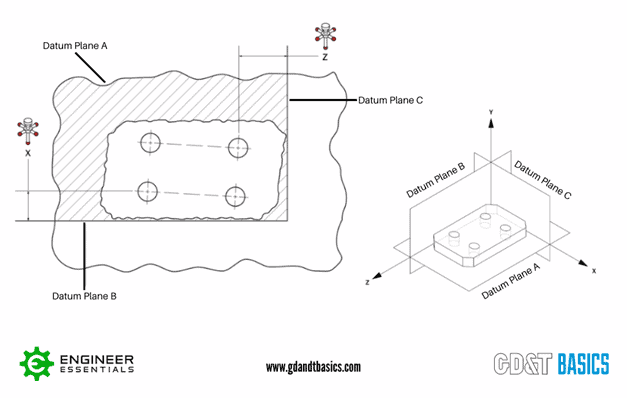
The example in Figure 1 shows a manufactured part with four holes and the datum reference frame (the “perfect grid”) for that part.
Using the Datum Reference Frame for Inspection
The datum reference frame creates our “perfect world” scenario of the part. So, how do we measure our imperfect part against this theoretically perfect world?
The order of the datums referenced in a feature control frame is important for the measurement of the part. The primary datum (commonly Datum A) will be the first to be constrained. It requires at least three points of contact, and controls three degrees of freedom.
The secondary datum (commonly Datum B) will always be perfectly perpendicular to Datum A. When measuring the part, the part must have 2 points of contact with Datum B. Datum B is constraining an additional two degrees of freedom.
The tertiary datum (commonly Datum C) will always be at 90 degrees to Datum A and Datum B. It is the last datum to be fixed during measurement.
So how is this done? We can virtually or physically simulate the datum reference frame and measure the part against it. Below, we will discuss simulating the datum reference frame for our example in Figure 1.
To measure our imperfect part, we would follow these steps:
First, we need to align our part to Datum A. A granite table can be used to simulate Datum A. Lay the part down on the granite table, and ensure that it has at least three points of contact. In Figure 1, Datum Plane A is the hatched area.
Next, we need to align our part to Datum B. Datum B can be simulated using a gauge block. Slide the part so that it butts up against the gauge block (Datum B), only to where it meets two points of contact. The part must be kept flush with Datum A, as it is the primary datum. With the part aligned to Datum A and Datum B, the part can now only slide in two directions – left and right. (See Figure 1.)
Last, we will align our part with Datum C. Virtually, what the CMM is doing is creating a flat plane perpendicular to Datum A and Datum B. It’s coming in until the part makes one point of contact to Datum C. Datum C is going to be 90 degrees from Datum B and from Datum A.
Now that we have simulated all three datums, we have built the Datum Reference Frame. We have aligned our part to the perfect world scenario. This is the most important step of the inspection, and now every measurement that is related to datum reference frame ABC will be measured against this perfect world scenario.
For our part in Figure 1, let’s say we have a position tolerance of 0.001 related to datums ABC. In a perfect world, these holes would have a basic dimension from our datums on our drawing – this is the perfect location for the four holes. When we’re placing our manufactured part on a CMM and aligning it to the datum reference frame, we’re seeing how well those four holes align with their perfect position. If the error is above 0.001, the part is rejected.
Summary
A manufactured part will never be perfect. As an inspector, your job is to compare the imperfect part to the perfect version of that part. To compare the two, we need a way to align our imperfect part to the “perfect world” represented by the part drawing. We are able to align this imperfect part by creating our datum reference frame ABC, and then aligning the part to the datums in that order: first aligning to Datum A, then Datum B, and finally, Datum C.
Interested in Receiving More Engineering Print and GD&T Tips
Sign up to join our mailing list and also receive a free GD&T Wall Chart
Join our Mailing List