
We receive many GD&T questions from our students, and in a recent live instruction webinar, we answered four that are commonly asked. We are now making this available to everyone in a four-part series on our blog and YouTube channel!
Previously, we answered the question:
Today we are answering question number 2:
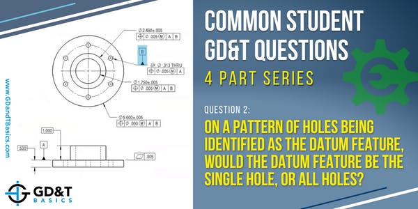
Question #2: On a pattern of holes being identified as the datum feature, would the datum feature be the single hole, or all holes?
We often see a pattern of holes as an assembly feature on a part. When a part is bolted down, the pattern of holes sets the location of that part. Because the bolt pattern is locating the part in the assembly, it is indicated as a datum feature on your GD&T drawing. An example of this is shown below in Figure 1, where we have a drawing of a flanged part with a pattern of bolt holes.

Figure 1: Flanged Part with a Pattern of Bolt Holes
You can see on the drawing that the datum feature symbol for Datum Feature B is placed on the leader arrow of the size dimension for the pattern of 6 holes. This leader arrow is pointing to a single hole, but this does not mean that the single hole is the datum feature. The size dimension that the datum feature symbol is associated with is for the pattern of holes, therefore the pattern of holes is the datum feature.
To inspect this part, we need to create the datum reference frame. The datum reference frame is the coordinate system, made up of 3 mutually orthogonal planes, created by the datums specified within a feature control frame. Our feature control frame shows Datum Feature A as the primary datum feature reference, and Datum Feature B as our secondary datum feature reference.
To simulate our datum reference frame, we need to first lock our part down on a surface that simulates Datum plane A, and secondly lock in to a Datum B simulator. For Datum Feature B, we want to locate the Datum B simulators (picture expanding collets) at the true position for each hole, which is defined by basic dimensions on the drawing. For the bolt circle, the true position of the holes would be defined using basic dimensions for the angular dimension between bolt holes and the radial diameter of the bolt circle (not shown on the above drawing view). These Datum B simulators would expand simultaneously so they engage each hole simultaneously – allowing each hole to have the same amount of control. Not one hole gets to dictate location more than the other. This is visualized in Figure 2.
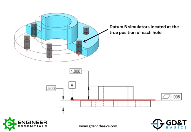
Figure 2: Datum B Simulators Centered at the True Position of Each Hole
The three mutually orthogonal planes that make up our datum reference frame for our part are illustrated below in Figure 3. The first orthogonal plane is Datum plane A, indicated in red. The other two orthogonal planes, created by Datum Feature B, are indicated in blue and green. The orthogonal planes for this datum reference frame are centered on the bolt pattern.
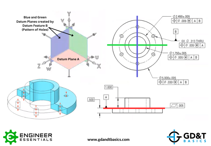
Figure 3: Datum Reference Frame created by Datum Features A and B
Conclusion
In summary, when a datum feature symbol is placed on the leader arrow of a dimension for a pattern of holes, the datum feature is the pattern of holes, not the single hole that the leader arrow is attached to. The datum simulators for this pattern of holes will be located at the true positions of the holes, defined by basic dimensions on the drawing. The resulting datums will be used to create the datum reference frame from which the part will be inspected.
For a more detailed explanation in answer to this question, watch the webinar recording linked below:
Stop hunting through pages. Get our GD&T Symbols Chart—your quick reference guide with every symbol on one page.
Save it to your desktop or print it out for quick reference. We’ll send the digital chart straight to your inbox. No spam, just helpful GD&T resources.
Get Your Free Chart