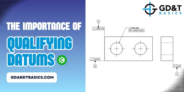
In this Question Line video, Jason discusses the positional control of the X, Y, and Z translations for a cylindrical post on the submitted drawing. He defines the datum reference frame and zero point of the part and explains why the feature control frame in question is essential to constraining where the cylinder exists vertically.
In this Question Line video, Jason discusses how datum targets, datum reference frames, and multiple datum structures can be of assistance in casting drawings.
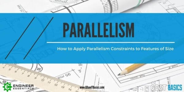
This video is in response to a question that we received on our question line from Jamee. Jamee’s question is as follows: “For parallelism of a circular feature of size (axis) can you use two...
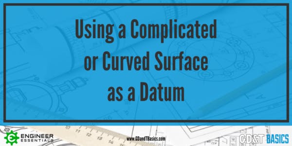
In this question line video – Tom discusses how to understand a curved profile surface as a datum for 4 holes that are required to remain normal to the irregular surface. How do we do...