Radial Patterns as Datums
by Crystal Bemis on May 4, 2026.
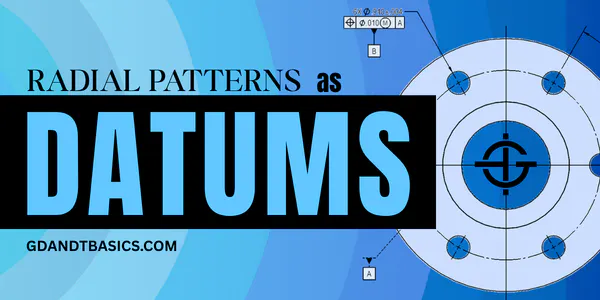
In this Question Line video, Jake demonstrates how to define radial patterns as datums, with guidance from ASME Y14.5.

In this Question Line video, Jake demonstrates how to define radial patterns as datums, with guidance from ASME Y14.5.

Jason explains how multiple features can be used to create a single datum on a part and why it’s done.

In this Question Line video, Jason explains how an irregular feature like a hexagon can serve as a primary datum feature and discusses how this part could be inspected – touching on gage design for manual inspection and point cloud analysis using a CMM.

Jason reviews the effects of tight position controls on features that relate to datum features with much larger form tolerances.
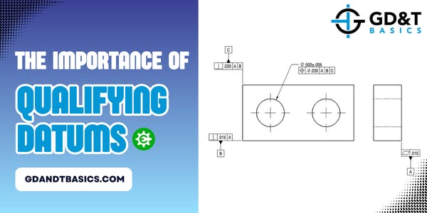
Jason explains how datums are qualified and the difference in how CMMs and physical datum simulators set up the datum reference frame.

In this Question Line video, Jason discusses reliable datum features. He explains that unreliable datum features can be avoided by following the functional intent of the part and walks through two drawing examples to explain the thought process behind selecting datum features.
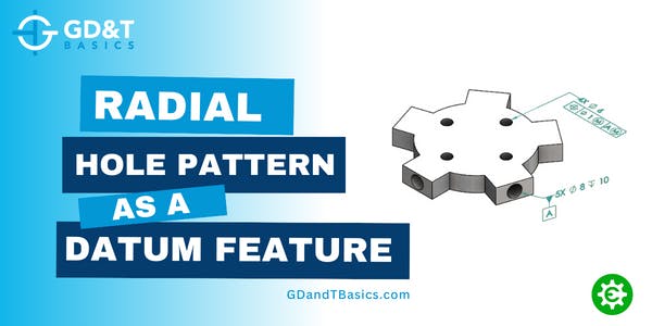
In this Question Line video, Jason responds to a question regarding radial hole patterns as datum features. He discusses how to set up the datum reference frame, how the datum reference frame controls degrees of freedom, and how to apply the Maximum Material Boundary.

Jason discusses how to select the appropriate datum feature when designing a hollow cylindrical part where both the ID and OD are mating features.

In this Question Line Video, Jason uses the example of a cylindrical datum feature to show how non-planar datums can be simulated and how they are able to constrain degrees of freedom.

Why doesn't a feature of size that is indicated as a datum feature need to be located? In this article and corresponding question line video, we look at two drawing examples to illustrate why datum features are not located.
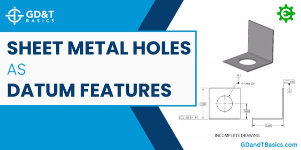
If I specify a hole in a practically thin feature, such as a piece of sheet metal, is this still considered a cylindrical datum? Is this a poor choice of datum? In this article, we look at an example to help us answer these questions.
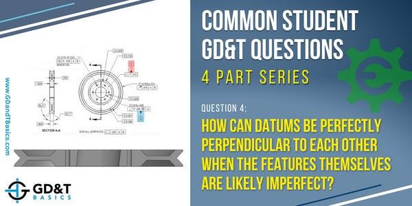
In this video, Jason explains how perpendicular datums can be derived from imperfect datum features.
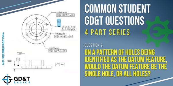
We often see a pattern of holes indicated as a datum feature in a GD&T drawing. How do we simulate this to create our datum reference frame?

Can a single point (without clocking) be used as a secondary datum in a feature control frame? To answer this question, we first need to determine what datum feature is being represented by this single point. Read on to discover the answer to this commonly asked question from our GD&T students.