
Why Use GD&T?
We get a lot of questions from students asking why they would want to use Geometric Dimensioning and Tolerancing (GD&T) over coordinate dimensions. Some believe that using GD&T will result in tighter tolerances and increase...
Get straight answers, useful tips, and clear explanations on our blog. It’s almost like getting GD&T training for free.

We get a lot of questions from students asking why they would want to use Geometric Dimensioning and Tolerancing (GD&T) over coordinate dimensions. Some believe that using GD&T will result in tighter tolerances and increase...
What is GD&T? If you are involved in design or manufacturing, you may be familiar with the term, “GD&T,” or “Geometric Dimensioning and Tolerancing”. Geometric Dimensioning and Tolerancing is a set of rules and GD&T...

Meet Jake DeVore, a GD&T instructor at GD&T Basics who brings real-world manufacturing and inspection experience—and a passion for teaching—into every class.
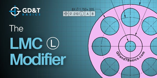
In this Question Line video, Jason explains how the LMC modifier impacts position tolerance, minimum wall thickness, and assembly clearance.

In this Question Line video, Jason explains surface vs. axis interpretation for positional tolerance at MMC and why ASME Y14.5 states to follow the surface interpretation when extreme form error is present.

In this Question Line video, Jason demonstrates how basic dimensions paired with profile of a surface create clearer, more functional surface control.

In this Question Line video, Jason breaks down what the MMC modifier does, how bonus tolerance works, and why there is minimal benefit of applying MMC on a threaded hole.

In this video, Jason walks through several examples to explain the various ways chamfers, edge breaks, and countersinks are dimensioned on a drawing and explains what tolerances apply under the ASME standards when none are specified in the field of view.
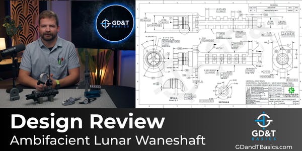
In this design review, Jason examines the application of GD&T and tolerancing strategy for the Ambifacient Lunar Waneshaft used in the Turboencabulator, focusing on functional intent, manufacturability, and inspection considerations.

In this Question Line video, Jason discusses how to approach situations where the CAD model and drawing information do not match, and how to determine which takes precedence.

In this Question Line video, Jason discusses two possible ways to control true position for an interrupted hole scenario, discussing UAME and Virtual Condition.
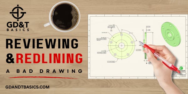
In this video, Jason reviews a bad drawing, walking through each error and explaining why it violates the rules of ASME Y14.5.
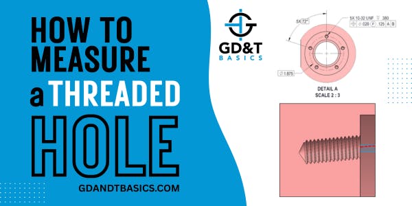
In this Question Line video, learn how threaded hole location gauges are used to inspect the pitch cylinder axis and why the projected tolerance zone modifier is often the most functional spec on an internal threaded feature.
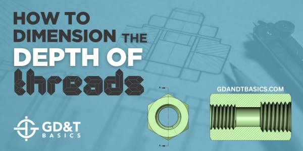
In this Question Line video, Jason explains how to properly dimension the usable depth of an internal thread and reviews methods for checking it on a part.
In this Question Line video, Jason explains why and how to use multiple features on a part to create one singular datum.
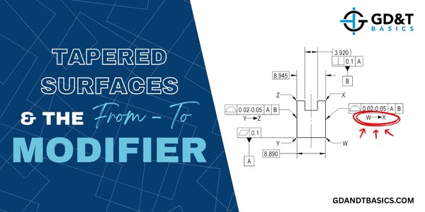
In this Question Line video, Jason demonstrates how the from-to modifier can be applied to create a wedge-shaped tolerance zone for tapered surfaces.

In this Question Line video, Jason reviews a simple part assembly to show how geometry and form factor into the tolerance stack-up analysis.
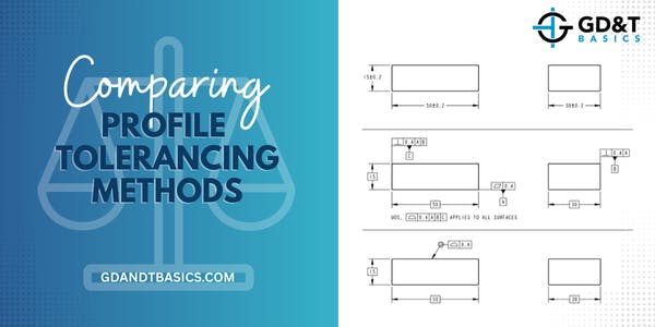
In this Question Line video, Jason reviews a submitted drawing toleranced three different ways and explains which option he would recommend.