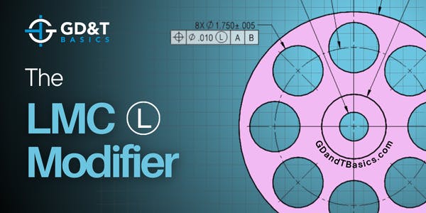
In this Question Line video, Jason breaks down what the MMC modifier does, how bonus tolerance works, and why there is minimal benefit of applying MMC on a threaded hole.
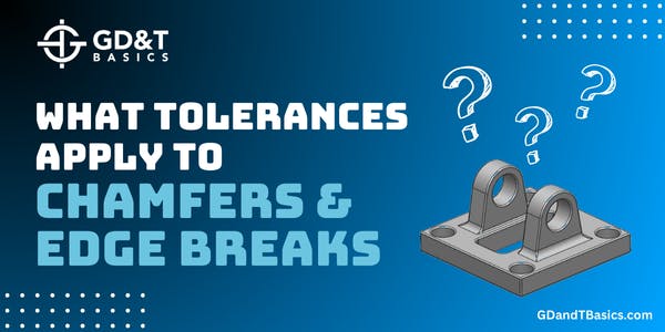
In this video, Jason walks through several examples to explain the various ways chamfers, edge breaks, and countersinks are dimensioned on a drawing and explains what tolerances apply under the ASME standards when none are specified in the field of view.
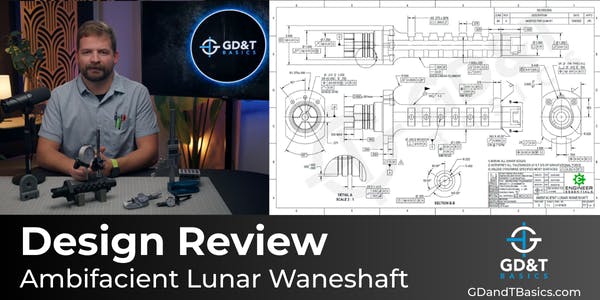
In this design review, Jason examines the application of GD&T and tolerancing strategy for the Ambifacient Lunar Waneshaft used in the Turboencabulator, focusing on functional intent, manufacturability, and inspection considerations.
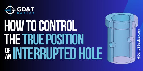
In this Question Line video, Jason discusses two possible ways to control true position for an interrupted hole scenario, discussing UAME and Virtual Condition.
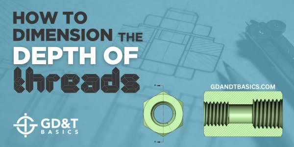
In this Question Line video, Jason explains how to properly dimension the usable depth of an internal thread and reviews methods for checking it on a part.
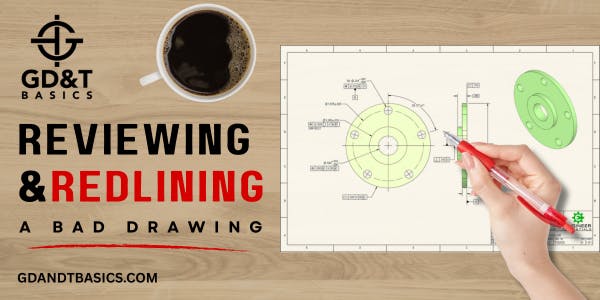
In this Question Line video, Jason reviews a submitted drawing, explaining the difference between flatness and parallelism, and gives options on how to tolerance the drawing based on what is critical to the design.
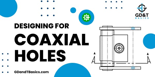
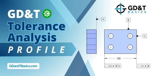
In this Question Line video, Jason reviews a submitted weldment drawing and demonstrates how to calculate the position tolerance needed for a zero-clearance fit in the worst-case assembly scenario, ensuring that the shaft can pass through two coaxial holes.
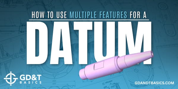
In this Question Line video, Jason explains how an irregular feature like a hexagon can serve as a primary datum feature and discusses how this part could be inspected – touching on gage design for manual inspection and point cloud analysis using a CMM.
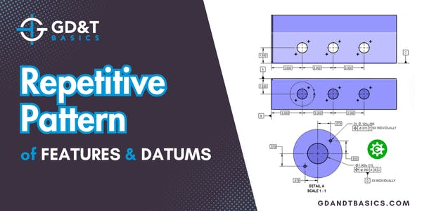
In this Question Line video, Jason discusses how to control a repetitive pattern of features with respect to a more central datum by using a “#X INDIVIDUALLY” note in conjunction with a datum feature.
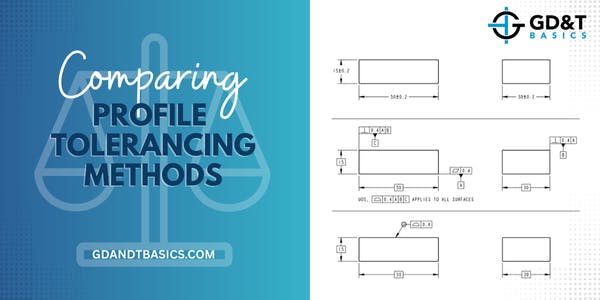
In this Question Line Video, Jason walks through a submitted drawing and clarifies how the feature control frames define the location and orientation of the tolerance zones for the profile of a surface control.
In this Question Line video, Jason reviews a submitted drawing that attempts to locate two parts relative to each other and explains how to choose the correct GD&T tolerances to support the intended function.
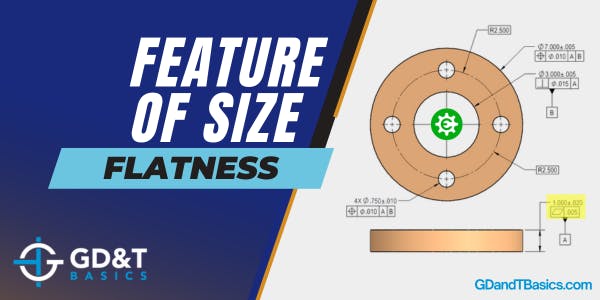
In this Question Line video, Jason compares flatness directly applied to a surface associated with a feature of size against flatness applied to a feature of size.
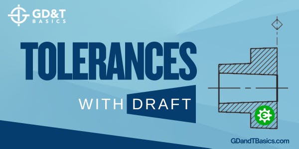
In this Question Line video, Jason introduces ASME Y14.8 and explains how to apply + or - DRAFT to size dimensions, using examples to show how to find and handle tolerances for draft features.
In this Question Line video, Jason explains how to calculate the flatness tolerance of a surface for a given example based on the size tolerances and Rule #1.
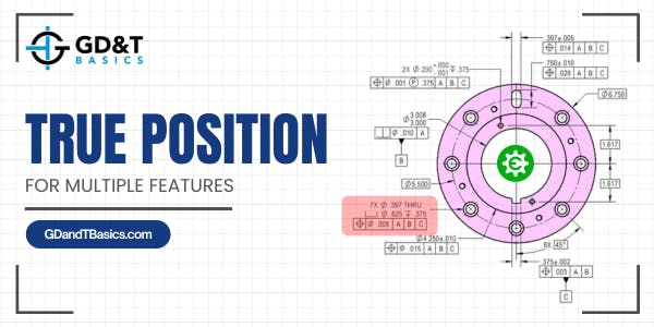
In this Question Line video, Jason walks through an example where one feature control frame is controlling position for multiple features and identifies where this practice is outlined in the ASME Y14.5 spec.
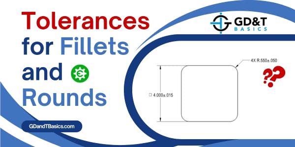
In this Question Line video, Jason discusses applying tolerances to fillets and rounds, explaining why applying profile of a surface allows more direct control of the size and form than using +/- tolerances.
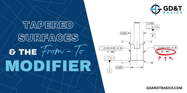
In this Question Line video, Jason discusses the ISO Unequal Zone (UZ) modifier, which is similar to the Unequally Disposed modifier of the ASME standard. He walks through an example where the UZ modifier is included in a feature control frame controlling profile of a surface and discusses how this impacts the tolerance zone.
In this Question Line video, Jason discusses the positional control of the X, Y, and Z translations for a cylindrical post on the submitted drawing. He defines the datum reference frame and zero point of the part and explains why the feature control frame in question is essential to constraining where the cylinder exists vertically.
In this video, Jason shows how to find the zero, or origin, for a given feature control frame. He walks through an example drawing that utilizes a single datum reference frame, describing how the datum reference frame fully constrains the part, noting that more complex parts may utilize multiple datum reference frames, resulting in multiple origin points.
In this Question Line video, Jason reviews how Rule #1 controls the size and form of a feature of size, and what this means for ring gage design and inspection reporting.
In this Question Line video, Jason discusses how datum targets, datum reference frames, and multiple datum structures can be of assistance in casting drawings.
In this Question Line video, Jason walks through a user-submitted symmetric part drawing. He discusses why the drawing is incorrect and how to fix it, noting that the symmetry symbol was removed from the ASME Y14.5 standard due to common misuse of the symbol.
In this Question Line video, Jason discusses reliable datum features. He explains that unreliable datum features can be avoided by following the functional intent of the part and walks through two drawing examples to explain the thought process behind selecting datum features.
In this Question Line video, Brandon walks through examples for both surface straightness and derived median line straightness, explaining how to correctly apply them and discussing design and inspection considerations.
In this Question Line video, Brandon explains the application of derived median plane (DMP) Flatness and discusses its frequent misuse and potential issues when used for stacking parts. He also provides an alternative for controlling flatness for stacking or symmetrical parts.
In this Question Line video, Jason reviews a drawing example to explain when Maximum Material Condition and Maximum Material Boundary modifiers may be applied.
In this Question Line video, Jason walks through a drawing that includes a position control on a pattern of holes (bolt circle), explaining what the feature control frame is and is not controlling.
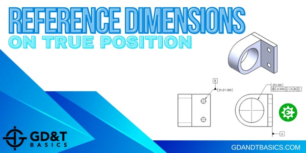
In this Question Line video, Jason walks through an assembly drawing to explain the scenario where a feature being controlled by position must have a reference size dimension rather than a tolerance on the size of the feature.
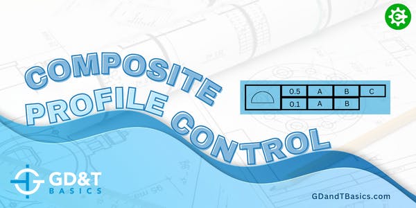
In this Question Line video, Jason discusses a composite feature control frame controlling profile tolerance. He walks through through the user submitted examples to explain the controls of each frame.
In this question line video, Jason explains how to control radial position with a composite tolerance by walking through an example of a pattern of holes on a cylinder.