
In this Question Line video, Jason answers the below question regarding how to interpret the composite profile lower frame:
I’m working on a part right now that my QC guy and I disagree on. I watched your video on Composite Profile feature control frames and I’m pretty sure I’m checking it correctly. How do I interpret the lower portion of the feature control frame in relation to the R.088 basic dim?
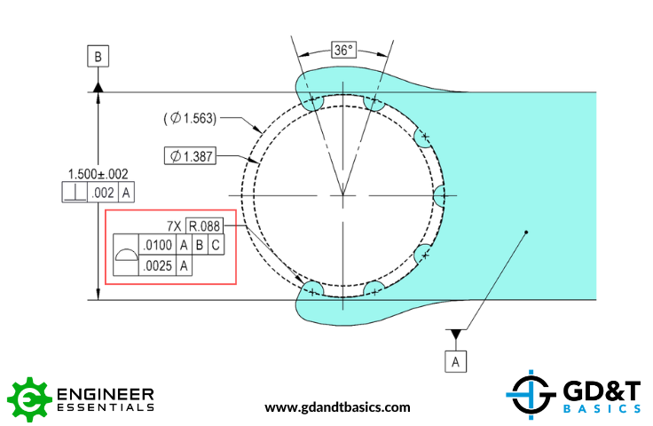
Jason reviews the submitted drawing, above, which includes a cutout with seven radially spaced features (teeth). The surface of each tooth has a radius of .088 and a composite profile control is being applied to this pattern of features. He explains how the upper frame of the composite profile fully constrains the pattern to the datum reference frame, controlling location, orientation, and form relative to the datums. He then mocks up the composite profile lower frame tolerance zone, explaining how it refines the pattern.
Jason also introduces a modification to the drawing where the composite profile is applied between X and Y, allowing the entire cutout —including the surfaces between the teeth—to be controlled as one feature. He then explains why this alternative approach may be preferred in some applications, particularly from an inspection standpoint where a functional gage can be used to verify the cutout.
For more information on Composite Profile:
Composite Profile with Unequally Disposed Tolerance
Do you have a GD&T question for our experts? Submit it at the link below:
https://www.gdandtbasics.com/share-your-gdt-questions/
If your question is selected, we will notify you when our video answer is posted to our YouTube channel.
* If you are a current student, reach out to us directly and we will get you into contact with your instructor. Active students’ questions receive a direct response within 24-48 hours.
The one-page GD&T reference that you will use every day
A visual breakdown of every core GD&T symbol and what it controls, all on one page. Bookmark it. Print it. Actually use it.
Download the Chart