
We receive many GD&T questions from our students, and in a recent live instruction webinar, we answered four that are commonly asked. We are now making this available to everyone in a four-part series on our blog and YouTube channel!
Previously, we answered the questions:
Question #1: Can a single point (without clocking) be used as a secondary datum in a feature control frame?
Today we are answering question number 3:
Question #3: Can my virtual conditions be the same diameter for a shaft (boss) and bore for the actual parts?
To answer this question, let’s first review Virtual Condition. Virtual Condition is a boundary defined by the size and geometric tolerances of a feature being controlled with Maximum Material Condition (MMC) or Least Material Condition (LMC) modifiers. This boundary is the envelope that the feature must be within in order to meet specification. If the feature deviates outside of this boundary, the part fails inspection and must be rejected.
In our example, we will be looking at features designed at MMC. Virtual Condition for a feature designed at MMC is calculated using the following equations:
VC (external feature) = MMC + Geometric Tolerance
VC (internal feature) = MMC – Geometric Tolerance
We will use Virtual Condition calculations to understand the amount of clearance between the two mating features.
Boss and Bore Assembly
Essentially, this question is asking whether mating boss and bore features can assemble if the features have identical Virtual Conditions. The short answer is, “Yes.” If the Virtual Condition for both parts are the same, this means that they have a zero-clearance fit in the worst-case scenario.
Let’s look at our example. In Figure 1, we have a part with a boss that is to assemble into the bore in the center of a pulley. To determine whether these will indeed assemble, we will calculate and compare the VCs of the boss and bore.
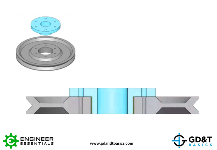
Figure 1: Assembly of Parts with Boss and Bore Features
Virtual Condition of the Boss
To calculate the VC of the boss for the part, detailed in Figure 2, we first need to determine the Max Material Condition of the boss. The Max Material Condition (MMC) is the condition in which the feature exists with the most amount of material allowed within the dimensional tolerance. For an external feature, this would be its largest allowable size. So, the MMC for the boss is equal to the Diameter plus the size tolerance.
MMC (boss) = 2.490 + .005 = 2.495
To then calculate the VC of the boss, we would add the MMC and the Geometric (position) tolerance.
VC (boss) = 2.495 + .005 = 2.5
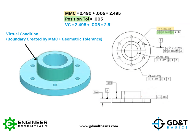
Figure 2: Calculating the Virtual Condition of the Boss
Virtual Condition of the Bore
Next, we need to calculate the VC of the bore. The drawing of the pulley with the bore feature is shown in Figure 3. First, we need to find the MMC of the bore. For an internal feature, the MMC is going to be the smallest allowable diameter of the feature. (Smaller hole = more material remaining) Therefore, the MMC of the bore is equal to the Diameter minus the size tolerance.
MMC (bore) = 2.51 – .05 = 2.505
To then calculate the VC of the boss, we would subtract the Geometric (position) tolerance from the MMC.
VC (bore) = 2.505 – .005 = 2.5
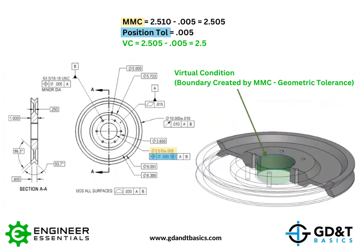
Figure 3: Calculating the Virtual Condition of the Bore
Assembly of the Boss & Bore Features
Now let’s look at assembling the two parts. We know that they will line up correctly because the datums are set up appropriately: Both the Boss and Bore diameters are dimensioned relative to Datums A and B, where Datum A for each part is the flat surface that will touch when the two parts are assembled, and Datum B for each part is the bolt circle. (This is visualized in Figure 4 with Datum A highlighted in red and Datum B in blue.) So, as long as the parts pass inspection (size and position), they will never deviate beyond virtual condition. Because both features have a Virtual Condition of 2.5, this means that at worst, there will be a zero-clearance condition.
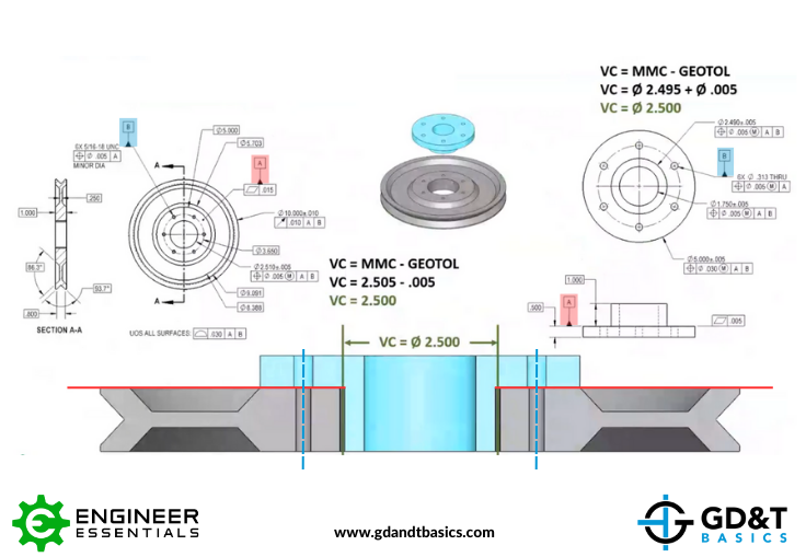
Figure 4: Comparing Virtual Conditions of the two Features
If you are the designer of the part(s), you can adjust the amount of clearance between the two parts by designing clearance into your Virtual Condition. For example, you may need to ensure more clearance in cases where lubrication between the parts is required. To do this, you would either increase the VC of the pulley bore diameter, or decrease the VC of the boss diameter. If you are buying the pulley and manufacturing the part with the boss, your option would be to ensure more clearance by shrinking the OD of the boss which would shrink its Virtual Condition.
In another case, you may want an interference or press fit between two features. This can also be ensured by changing the VC of the two features so that they overlap.
Summary
Comparing Virtual Conditions of mating features will help us understand the potential clearance between the parts when assembled. When there is a clearance between the two features’ Virtual Conditions, there is an ensured clearance for the assembled parts. On the flipside, an interference fit can also be ensured by adjusting the VCs of the features.
In conclusion, the answer to the question, “Can my virtual conditions be the same diameter for a shaft (boss) and bore for the actual parts?,” is “Yes.” Having identical Virtual Condition values for the mating features would mean that there is zero clearance between the two features at the worst-case scenario.
For a more detailed explanation in answer to this question, watch the webinar recording linked below:
Stop hunting through pages. Get our GD&T Symbols Chart—your quick reference guide with every symbol on one page.
Save it to your desktop or print it out for quick reference. We’ll send the digital chart straight to your inbox. No spam, just helpful GD&T resources.
Get Your Free Chart