Loading countdown timer...
Psst —10% Off Online Courses with Code GDT26FUN, All July Shop Online Courses

Navigating Your GD&T Reference Guide

How to read your GD&T Symbols Chart without guessing.

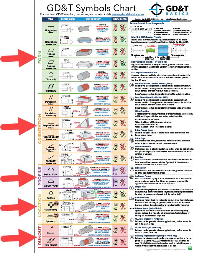
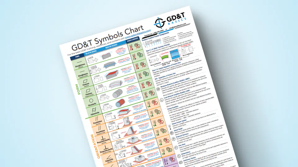
This chart gives you fast access to all 14 tolerance controls, including, what each symbol means, how it looks on a drawing, what it controls, and when datums are required.

Here's how to read it.

Section 1

How the Chart is Organized

The main chart covers all 14 GD&T tolerance controls, organized into five categories based on what they control. Once you know which category a symbol falls into, you already know something about what it does.

Form Controls

Green rows · Straightness, Flatness, Circularity, Cylindricity
Control the shape of a feature by itself — no datums required. These form controls will never reverence any datums. These tolerances only care about the feature’s own geometry, not where it sits on the part.

Orientation Controls

Orange rows · Parallelism, Perpendicularity, Angularity
Control how a feature is angled relative to a datum. At least one datum is always required — these controls are meaningless without something to be parallel, perpendicular, or angled to. Orientation controls do not locate a feature; they only control its angle.

Profile Controls

Purple rows · Profile of a Line, Profile of a Surface
Control the shape of a surface or cross-section relative to a true profile. Profile of a Surface is one of the most versatile controls in GD&T — it can simultaneously control form, orientation, and location in a single callout. Datums are optional but common.

Location Controls

Yellow rows · Position, Concentricity, Symmetry
Control where a feature is located relative to datums. Position is the most widely used control in GD&T — it defines where a hole, slot, boss, or tab must fall within a tolerance zone (even controls spheres!). Datums are always required (unless youre controlling a pattern of features and dont care where that pattern ends up).
Note: Concentricity and Symmetry were removed from ASME Y14.5-2018. If you’re working to the 2018 standard, Consider using other controls like Position or Runout instead. Concentricity and Symmetry are still valid on drawings that reference an older revision — always check the title block.

Runout Controls

Red rows · Runout, Total Runout
Control how much a surface wobbles around a datum axis during rotation. Measured by spinning the part and inspecting the surface with a dial indicator. The go-to controls for shafts, bearings, and any rotating components.

Section 2

What Each Column is Telling You

Each row of the chart is one tolerance control. 
Every row gives you four things, and they build on each other left to right.

Column 1

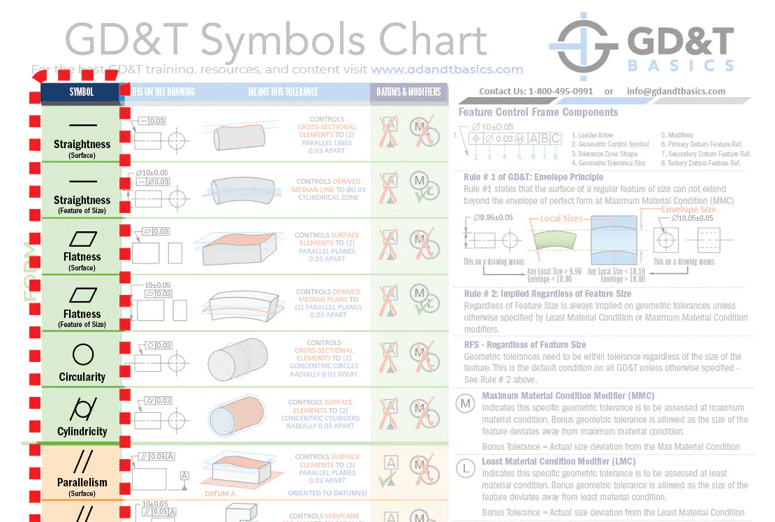
Symbol + Name


The first column shows the GD&T symbol itself alongside the name of the tolerance control it represents.

This is your anchor. Every other column in the chart is explaining this one entry. 

If you're starting from a symbol on a drawing, match it here first. If you're starting from a concept (like "I need to control how flat this surface is"), scan the names to find the right row.

Pay attention here: some symbols appear twice in this column — once applied to a surface and once applied to a feature of size. That distinction matters, because the same symbol means something different depending on how it's called out on a drawing.

The Drawing Callout

Column 2

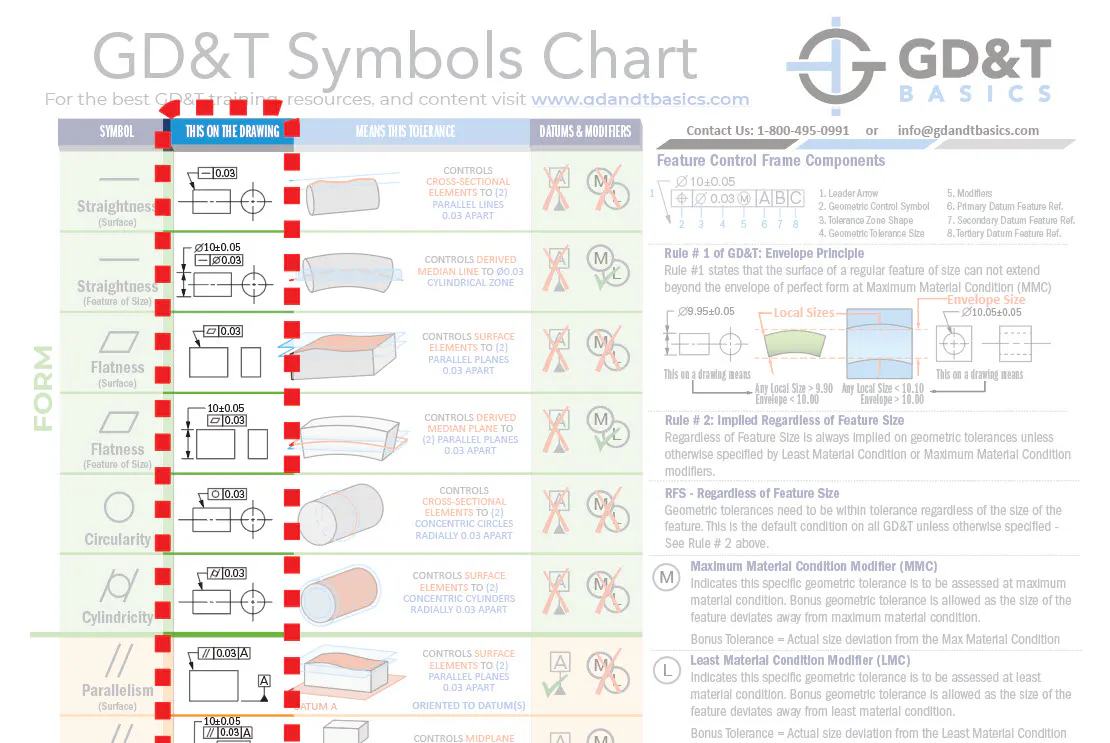
What It Looks Like on a Drawing

Column 2 shows the symbol placed in a real feature control frame, applied to actual part geometry, as it would appear on an engineering drawing. 

The geometry is simplified on purpose. The focus here is recognition: can you find this callout when it shows up on a drawing in front of you?

If a symbol appears twice in Column 1, it will appear twice here too. Once for the surface application, once for the feature of size application. The drawing will look different for each.

Column 3

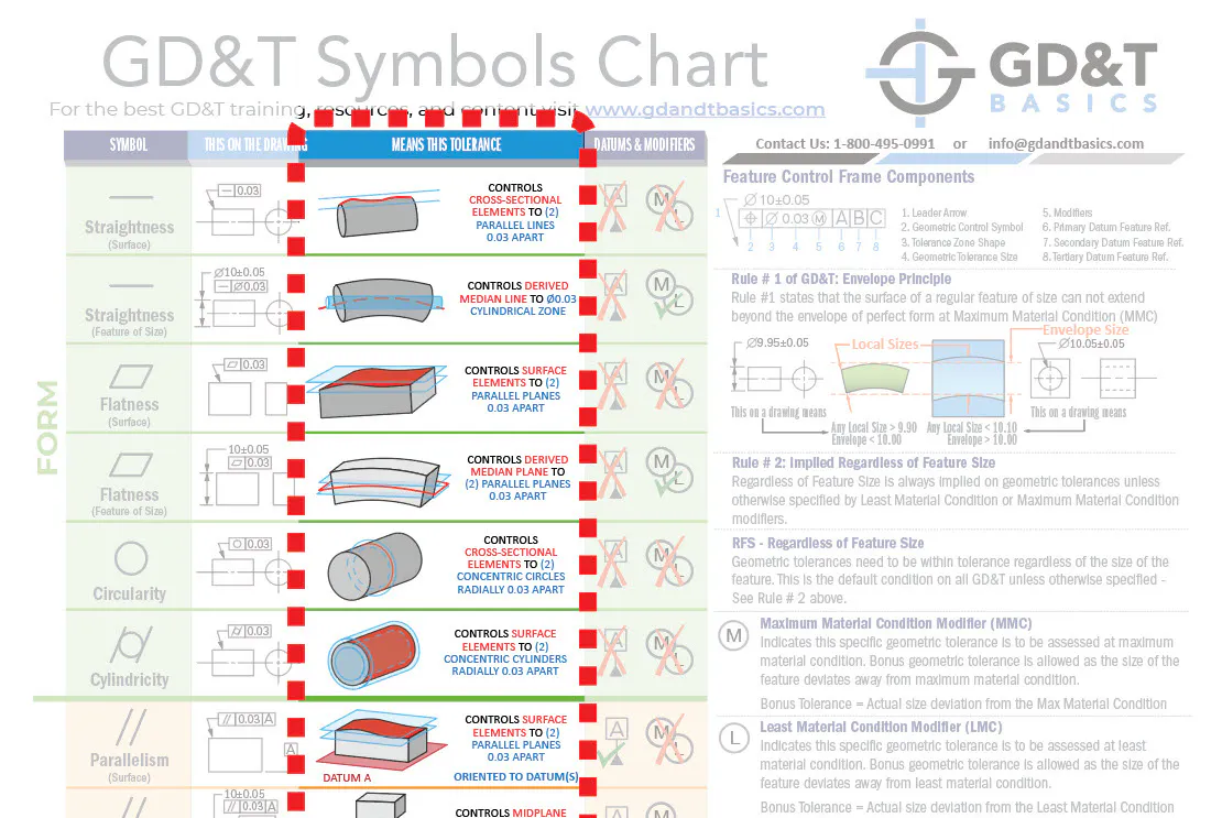
What the Tolerance Actually Controls

Column 3 highlights what the tolerance is actually controlling. 

The elements being controlled are shown in red: the feature or surface the callout applies to. The tolerance zone itself is shown in light blue: the invisible boundary the part must conform to.

The text alongside the graphic describes this in plain language. For example: "Controls surface elements to two parallel planes 0.03 apart." This is the translation from symbol to meaning. What an inspector is actually measuring when they check this callout.

Column 4

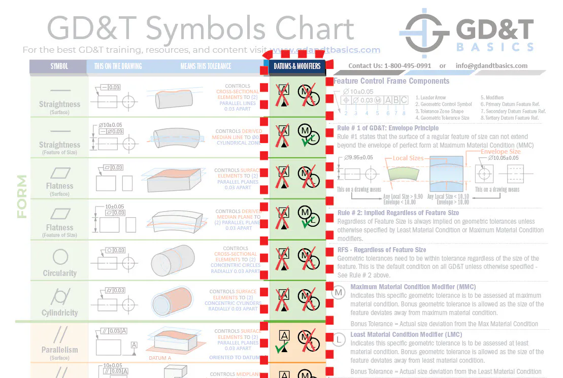
Datums & Modifiers


This column tells you two important things: whether the tolerance can reference datums, and whether material condition modifiers (like MMC or LMC) can be applied. 

  • If datums can be referenced, the control in question will affect the orientation and/or the location of the controlled feature relative to those datums. 
  • If modifiers are allowed, it means a feature of size is involved and bonus geometric tolerance may be available based on the actual measured size of the feature. 

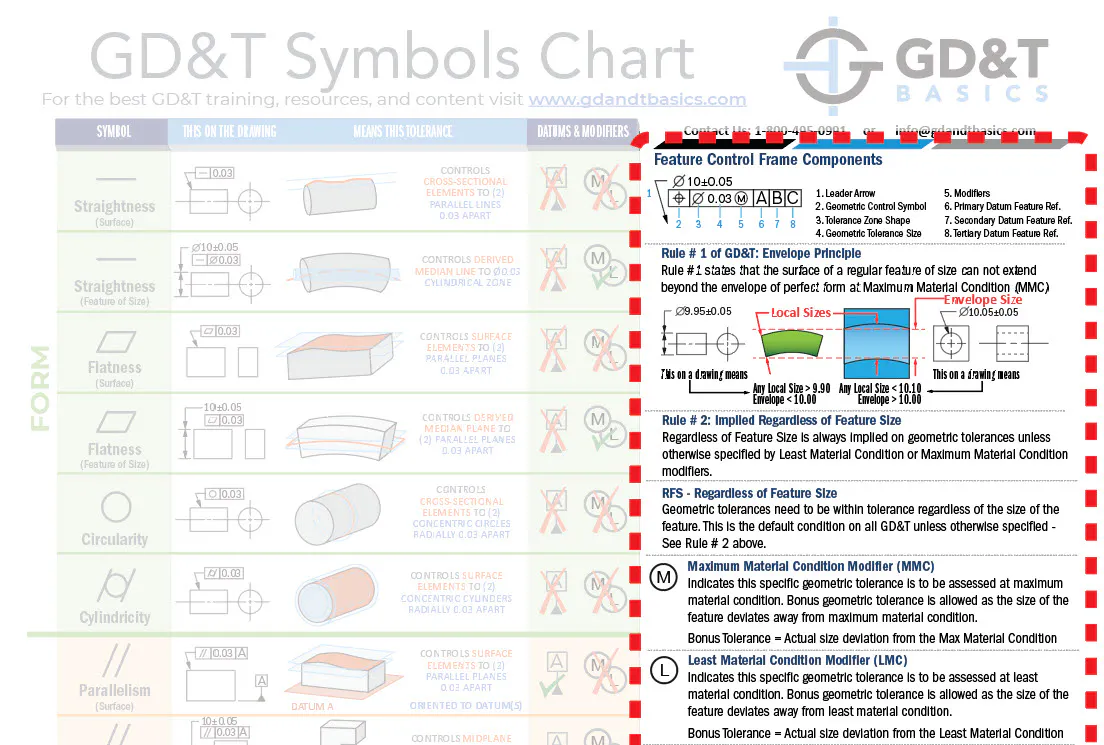
Check out the right side of this chart to reference the foundations of the Maximum Material Condition Modifier (MMC) and the Least Material Condition Modifier (LMC).

If you're not sure what those symbols mean, the right side of the chart has a reference section for exactly that.

The Right Side of the Chart

Rules, Modifiers & Supporting Symbols


The right side is a reference section for the concepts that make the rest of the chart work. The ones that show up constantly on drawings but don't get their own row.

Here you'll find the material condition modifiers MMC and LMC, which unlock bonus tolerance and are essential to understanding how GD&T interacts with part size. 

You'll also find the datum feature symbol and datum targets, which are the building blocks of any measurement reference frame. 

Rounding it out are a handful of specialized modifiers and symbols — including Projected Tolerance, Free State, Tangent Plane, Independency, and more — each of which changes how a tolerance is interpreted or applied in specific situations. 

Whether you're decoding a drawing you've never seen before or double-checking your own callouts, this section gives you quick access to the context you need to get it right.

Supporting Concepts Reference

Reading a Feature Control Frame

The rectangular box that houses the geometric symbol, tolerance value, and datum references. Knowing how to decode it is the single most important skill in reading GD&T. The chart identifies all eight components: Leader Arrow, Geometric Control Symbol, Tolerance Zone Shape, Geometric Tolerance Size, Modifiers, and Primary, Secondary, and Tertiary Datum Feature References.

→ Learn more about Feature Control Frames

Rule #1 — The Envelope Principle

The surface of a regular feature of size cannot extend beyond the envelope of perfect form at MMC. Even if local sizes vary within tolerance, the overall shape must stay within perfect form at its largest allowable size.

→ Learn more about Rule #1 in GD&T

RFS — Regardless of Feature Size

The default condition for all GD&T. Geometric tolerances apply regardless of the feature’s actual size unless MMC or LMC is explicitly called out. Rule #2 formalizes this.

→ Learn more about Rule #2 / RFS

Maximum Material Condition (MMC)

Geometric tolerance applies at the feature’s largest permissible size for external features, smallest for internal. As the feature departs from MMC, bonus tolerance is earned. Bonus Tolerance = actual size deviation from MMC. One of the most powerful and commonly misunderstood tools in GD&T.

→ Learn more about MMC

Least Material Condition (LMC)

The counterpart to MMC. Bonus tolerance is available as the feature departs from its LMC size. Less common than MMC but important in specific applications. Bonus Tolerance = actual size deviation from LMC.

→ Learn more about LMC

Virtual Condition

A fixed boundary that accounts for both size and geometric tolerance. Used in assembly analysis to ensure parts fit regardless of actual produced sizes and location deviations.
For holes: Virtual Condition = MMC − Geometric Tolerance
For pins: Virtual Condition = MMC + Geometric Tolerance

→ Learn more about Virtual Condition

Datum Feature Symbol

Identifies a physical surface or feature of size that serves as a reference for measurement. Datums are the foundation of your part’s coordinate system — everything else is measured relative to them.

→ Learn more about Datum Feature Symbols

Datum Target

Used when a full surface isn’t practical as a datum. Instead, specific points, lines, or areas are designated to establish the datum. Common in casting and forging applications where full surface contact isn’t reliable.

→ Learn more about Datum Targets

Projected Tolerance

The tolerance zone extends above the surface of the part to a specified height, simulating the virtual condition of a threaded stud or press-fit pin in its mating part. Used commonly with Position.

→ Learn more about Projected Tolerance

Free State

Indicates a dimension should be measured in an unrestrained condition. By default all GD&T is evaluated in the free state — this modifier is mainly used to call it out explicitly when a restraint note has been applied, or when there’s any chance of ambiguity.

→ Learn more about Free State

Independency

Overrides Rule #1. When applied, the geometric form tolerance of a feature is no longer constrained by the feature’s size limits. Size and form are evaluated completely independently of each other.

→ Learn more about Independency

Continuous Feature

Treats two or more separate features as a single uninterrupted feature. Rule #1 and any geometric controls apply as if the features were one continuous surface or feature of size.

→ Learn more about Continuous Feature

Tangent Plane

Instead of requiring the entire surface to fall within the tolerance zone, only a theoretical tangent plane — established by the surface high points — needs to be in tolerance. Useful for mating surface applications where only the high points make contact.

→ Learn more about Tangent Plane

Basic Dimensions

Dimensions shown in a rectangular box that are theoretically exact. They carry no tolerance themselves — the GD&T control associated with the feature defines the allowable deviation. You’ll see these constantly with Position and Profile callouts.

→ Learn more about Basic Dimensions

Between Symbol (Profile tolerances only)

Specifies that a profile tolerance applies only between two identified points on the drawing, rather than to the entire feature. The two extremities are labeled in a single view.

→ Learn more about Profile Tolerances

All Around Symbol (Profile tolerances only)

Indicates the profile tolerance applies to every surface visible in the specified view, going all the way around the part’s perimeter in that view.

→ Learn more about Profile Tolerances

All Over Symbol (Profile tolerances only)

Like All Around but in 3D — the profile tolerance applies to every surface of the entire part in every view.

→ Learn more about Profile Tolerances

Unequally Disposed Profile

Shifts the profile tolerance zone so it’s no longer symmetric about the true profile. The value PRECEDING the symbol is the total tolerance. The value FOLLOWING indicates how much of that tolerance is shifted in the material-adding direction.

→ Learn more about Unequally Disposed Profile

Note on Concentricity and Symmetry: These controls were removed from ASME Y14.5-2018. If you’re working to the 2018 standard, Position or Profile of a Surface are used instead. These symbols are still valid on drawings that reference an older revision. Always check the title block.

Ready to Take Your GD&T Knowledge Further?

Our courses teach you how to apply GD&T with clarity and confidence in real-world situations.