
Symbol:
Category: Feature of Size
Definition:
Least material condition is a feature of size symbol that describes a dimensional or size condition where the least amount of material (volume/size) exists within its dimensional tolerance. The callout also overrides GD&T Rule#2 or the Regardless of Feature Size rule.
For simplicity:
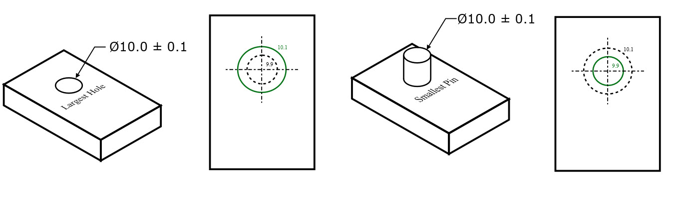
If it is a hole or internal feature: LMC =Largest hole size (least material in part)
If it is a pin or external feature: LMC = Smallest size of the pin
Least Material Condition is one side of the dimensional limits on a part. The other side of the tolerance range would be the Maximum Material Condition.
If you want to ensure that two always have contact or a press fit Least Material condition can be called out. It is most often the control of parts that are pressed together to ensure that they always have a snug fit and no clearance.
If you made sure that the LMC of the shaft was always larger than the LMC of the hole, you ensure that there will always be a tight fit between the parts. This creates a condition where you can use a functional gauge to ensure that the external feature is not too small or that the internal feature is too loose.
Use in Geometric Dimensioning and Tolerancing:
Least Material Condition is fairly rare in geometric dimensioning and tolerancing. There are only a few reasons why a LMC should be called. The most common reason for calling it would be that you have a hole or other internal feature that is very close to the edge of a part. If you call LMC with true position in figure 2 below – you would be specifying that if the hole is at its largest size, it can only vary by as much as the true position tolerance.
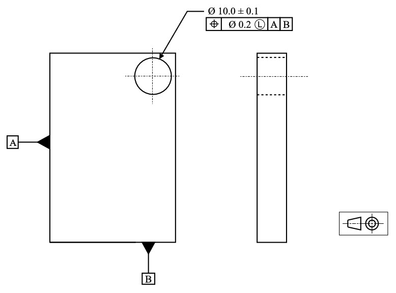
Thin Wall Hole Example
However if the hole is smaller than its Least Material Condition, you can apply a bonus tolerance to the part, because now the true center of the hole can be closer to the edge, without minimizing the thickness of the material.
Concept of LMC with No-Go Gauges
The concept of the least material condition (not the GD&T symbol)comes in handy when a functional gauge is needed to control a part. If you want to limit the size of your feature to insure a proper fit, you can specify the least material condition callout and control it with a specific type of gauge called a No-Go Gauge.
For example if you wanted to ensure that a pin always has a tight fit into a hole, you could design the No-Go hole gauge to mimic the least material condition of the part. This would be a block with a hole of a diameter equal to the pin’s LMC (min Ø). To check the part you would try to insert the pin into the hole. If it doesn’t fit (No-Go) then you know that the pin is large enough to be a tight press fit into the feature.
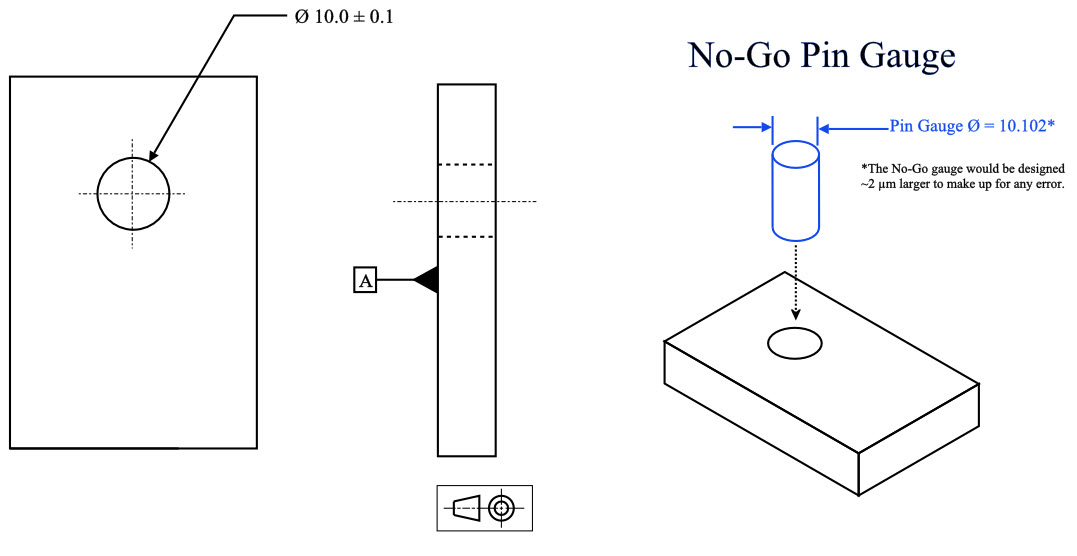
A No-Go gauge for a hole would use a pin gauge = Hole’s Max Ø
A No-Go gauge for a pin would use a ring gauge = Pins Min Ø
Cannot Combine Gauging with GD&T Symbols
Here is where the weakness of LMC comes out. In maximum material condition you are defining that the size cannot go past the max material size + the geometric callout. This works fine because you are using two tolerances that are positive. However with least material condition this you cannot create a functional gauge that controls both.
For example if you have a perpendicularity callout and want to also control LMC on a hole, you can check the hole for size with a no-go gauge to ensure it is small enough for a press fit. However if you specify a gauge that allows for a bonus tolerance on the least material condition, you cannot make a no-go gauge also check the perpendicularity, because a No-Go gauge is designed not to fit!
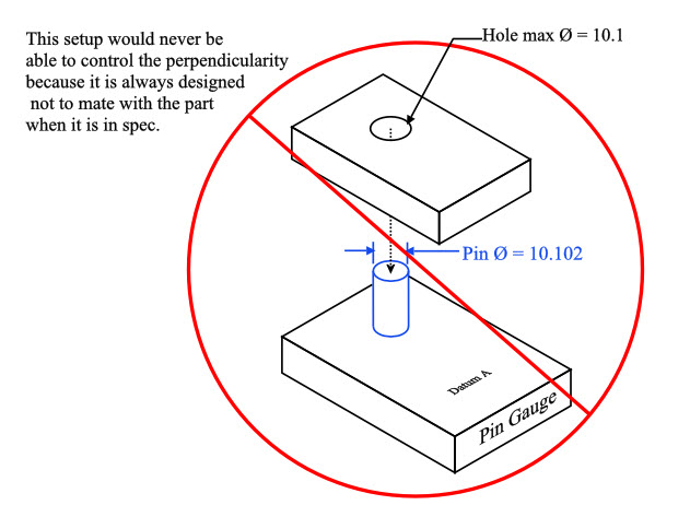
The problem is that GD&T symbols always specify the maximum amount that a part can vary and cannot be combined when you are controlling the a least material control of size. The only way LMC can be called on a feature would be if the least material condition and the perpendicularity were measured and calculated separately. This, however, eliminates the benefit and speed of a gauge.
For these reasons least material condition is seldom used as a control for geometry and size. While gauging is always possible for least material condition size in a production environment, you cannot gauge for both GD&T and dimension at once.
The takeaway should be that in GD&T understanding least material condition as a concept of size is important. The only time you will truly see it is combined with true position on thin walled parts like in the Thin Wall Hole Example above.
Final Notes:
Rare Usage:
Least material condition should only be used when absolutely needed, due to not being able to accurately gauge for size and geometry at once. Least Material Condition is really only used to ensure there is enough thickness between the edge and the inside of the hole.
Features of Size
Least Material Condition is one of three features of size callouts in Geometric Dimensioning and Tolerancing. The other two are Maximum Material Condition and Regardless of Feature Size. All of these specify the condition that the part or feature must be in to apply the specified tolerance.
Regardless of feature size as default
When there is no callout to Maximum Material Condition or Least Material Condition, all parts default to regardless of feature size, meaning the geometric controls exist regardless of how large or small the part dimensions are.
Be The Go-To Engineer at Your Company
Learn GD&T at your own pace and apply it with confidence in the real world.
Get GD&T TrainingAll Symbols


Hello Sir,
If we are using ring gauge as a No-Go gauge to measure least material on pin, only both ends of pin will be checked. How will we ensure that in between points will be least material only, it can be less than desired LMC?
a set of two-point caliper measurements would suffice for this – every one of them would need to be greater than LMC
I have an application for LMC that’s not discussed here.
The part has a hole in it that a pin drops into place and holds a spring. The spring will be pulled into tension and the force matters. Any positional change of the hole will change stretch of the spring, and thus it’s forces. Likewise, if the hole is over-sized the pin will shift to the one side due to spring forces, and reduce the force of the spring. So MMC in this case would be the worst option, because the larger the hole the more it can shift, doubling up on how it affects the spring forces. However, if you were to use LMC in this application, when the hole size is the largest (allowing pin to shift more), the tolerance band would be the smallest so not affect it as much.
Of course, its still possible to use MMC (or RFS) as long as there is enough leeway in the system (or designed into it) to allow it. But this is a different case where MMC isn’t the best and LMC would actually be better.
Hey JP – This is a great application! I am so glad you shared this with us. LMC is so much more rare than MMC in the industry – but this is a really interesting application that fits the concept really well!
HI,
In geometric tolerance, what is the definition of ø 0.2?
is it plus or minus 0.2 ?
or other?
Thirumoorthi –
Geometric tolerances that have a diameter symbol in front of them indicate that your tolerance zone is cylindrical. As long as the axis of the hole exists entirely within the aforementioned cylinder your part is in spec. The axis of the hole is free to shift and tilt in any manner so long as no part of the axis falls outside the tolerance zone.
Please check out our GD&T Basics Course! We have a number of price points to meet any need and our team is currently hard at work refining our advanced course. There is material for every skill level. Please check back at any time.
I hope this helps.
Cheers,
Matt
I still don’t understand L or M and I feel you can achieve the same with tolerances
James –
Ok, so first lets talk about MMC vs LMC in the feature control frame, not next to the datums. This is essentially telling you what material condition the tolerance is to initially be taken at. MMC is the max material condition, or the condition that results in the heaviest version of the part. Smallest internal feature, largest external feature. According to the standard as you depart MMC (or LMC) you get a ‘bonus’ tolerance equal to the amount of departure from the stated condition. If you have a tolerance of .050 at MMC and a hole size of 2.65 +/-.02 you MMC would be 2.63 and your tolerance for that hole would be .050. Then as you move away from MMC you gain tolerance like so: For a 2.65 hole you get .070 worth of tolerance and at 2.67 hole size you get .090.
As a thought exercise please do the following as if you were locating the center of a hole. Create a traditional cartesian coordinate system (that is X and Y axes). For an arbitrary part we are going to say it has a dimension D +.5/-.5 in both the x and y direction. What matters here is the tolerance zone for the location of the hole. You now have a square zone of area 1 that the center of your hole has to be located in. This is the method you are used to seeing.
Now, draw a circle around this box such that the four corners of the box touch the insides of the circle. Which of the two shapes has a greater area? The circle right? If you do the math you’ll find that it’s bigger by about 57%. Why does any of this matter? Because someone at some point sat down and thought that using the traditional method if they had a part with hole axes located at the corners of the box located a distance r = sqrt (.5^2+.5^2) why can’t that apply to the full 360 degrees of the tolerance zone vs just four corners?
It’s through this method that you get to keep the same tolerance you’ve always had, but by applying it to a cylindrical tolerance zone vs a square one you actually gain 57% in terms of area for good hole axes to fall into. This means fewer rejected parts and less money out of your pocket!
This is a lot to throw at you, but I would encourage you to consider taking our Fundamentals of GD&T course offered on our website. There is a wealth of information that is only going to help you be better at your job.
If you have further questions please don’t hesitate to ask.
Cheers,
Matt
How would we dimension the hole size so the machinist aims for LMC
Soozi –
If you have a 1 inch hole and want to make sure that the machinist aims for that value you can do this using tolerances. For instance: 1 +.000/-.050 Every dimension must have a tolerance, whether directly stated or as part of a feature control frame. Using this method indicates to the machinist that the design works best at 1 and nothing more. There are several ways of doing this and this just represents the simplest method.
I hope this helps answer your question.
Cheers,
Matt
Thanks Peter Torresani
May anyone explain bonus tolerance with LMC, with calculations and physical interpretation.
I’m always amazed at how poorly the application of LMC is understood. Years ago I discussed it with one of the people on the ASME board, and he didn’t understand the practical applications either. The rule of thumb for the the material conditions is pretty simple. If the goal is to ensure two features fit together, use MMC (most common). If the two features self-center as with a flat heat screw or press fit dowel, use RFS. And to the point of this comment, if the goal is to ensure that when assembled the two features will align something properly, use LMC.
For example, if you have a corner positioning block with clearance holes for dowels, the reason for the dowels and holes is to ensure that the outer edge of the block is within a allowable range when installed. If the clearance holes are bigger, there is more movement between the dowel and hole, so you cannot allow as much positional tolerance to the hole. Another way to understand it is that the walls of the clearance hole can only extend so far from the center of the dowel. The bigger the hole, the less the center of it can move.
This example is nice, because it provides a use for RFS (the press fit dowel hole) and MMC (the clearance hole for the screws holding the block in place.
Peter –
Good rules of thumb you’ve summarized the needs for each modifier pretty well. The other classic example of using LMC is when you are trying to maintain a minimum wall thickness for some application.
Thanks for contributing.
Cheers,
Matt
Thanks. Nice thumb rule
what i understand about LMC is, it is provided for the features (like holes in flywheel) which does not have any significant function, yet we wan to maintain the wall thickness. Can you please give me more examples where LMC is used for better understanding?
I’ll be honest – other than maintaining wall thickness and clearances, it really does not have many more uses as there are rarely situations where you want your geometric tolerance to get bigger as the part approaches the MMC size. MMC is probobly used 95-99% of the time compared to LMC (depending on the industry you are in as well)
This is the best way you made me understand about LMC .Thanks 🙂
Hi, Thank you for your useful content. when I read about (LMC); I don’t understand usage of it’s (LMC) in GD&T. Is it possible for you that display this issue in figure with dimension.
LMC is not too common in GD&T mainly for the reason that it is usually the opposite of what you would like to exist functionally. One use for LMC that helps to understand when it should be used is for when you are adding a hole to a flywheel. You are not inserting anything in the hole, its only there to minimize weight. Your main goal then is to make sure that the hole does not get too close to the edge of the flywheel that the wall thickness is too small. Often times with LMC you are making sure you have enough “meat” in a structure so that it is not too weak. This is one application, but it is probably the most common use.
Thank you; but I don’t understand yet.