
In this Question Line video, Jason answers the following questions regarding profile tolerancing methods:
I have three questions regarding how to tolerance the profile of a part shown in the attached drawing.
- What are the key differences among the three profile tolerance approaches?
- Do they control the part to the same level of accuracy?
- Which method would you recommend as the preferred practice, and why?

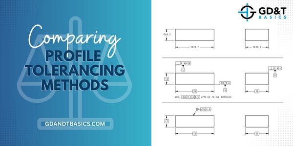
The submitted drawing, shown above, includes a simple part toleranced in three different ways. The first example includes size dimensions with plus/minus tolerances. The second example is controlled using flatness and perpendicularity tolerances. The third example is controlled by the profile all over symbol. Jason walks through each example describing how the tolerances control the part and explains which option provides the most clarity, most direct calculable tolerances, and most direct way of inspecting all surfaces.
Looking for answers to your GD&T questions? Submit your question to our GD&T experts at the link below!
https://www.gdandtbasics.com/share-your-gdt-questions/
If your question is selected, we will notify you when our video answer is posted to our YouTube channel.
* If you are a current student, reach out to us directly and we will get you into contact with your instructor. Active students’ questions receive a direct response within 24-48 hours.
The one-page GD&T reference that you will use every day
A visual breakdown of every core GD&T symbol and what it controls, all on one page. Bookmark it. Print it. Actually use it.
Download the Chart