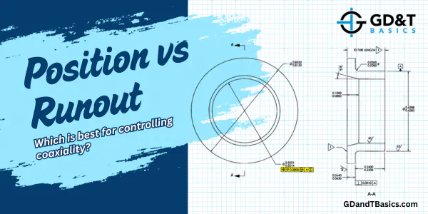
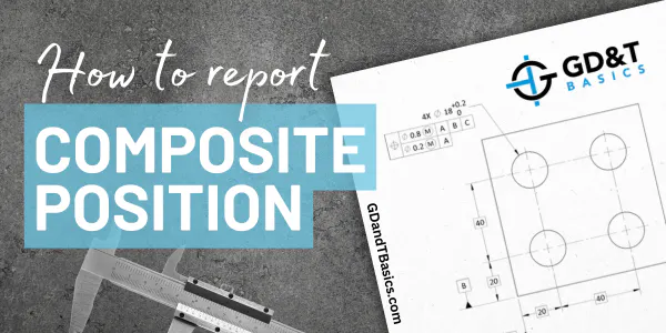
In this Question Line video, Jason explains how to report composite position for a pattern of holes, focusing on the challenges and methods of reporting results for the lower framework (FRTZF).
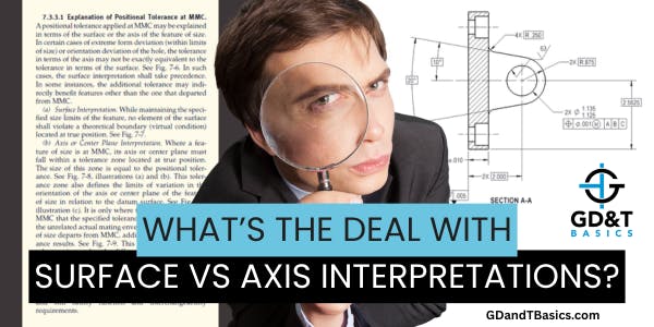
Jason explains surface vs axis interpretations in positional tolerance at MMC, showing how ASME Y14.5 handles extreme form error and inspection decisions.
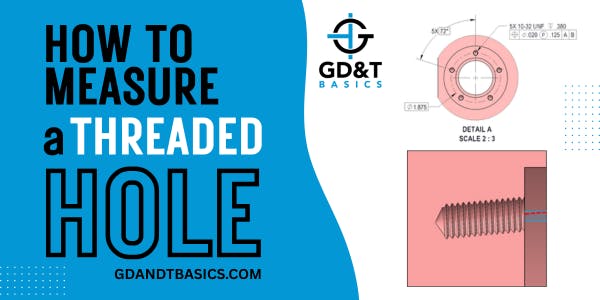
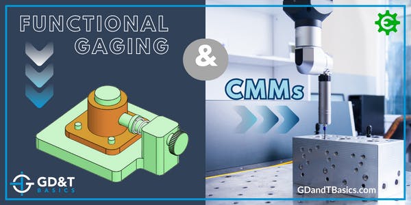
In this Question Line video, learn how threaded hole location gauges are used to inspect the pitch cylinder axis and why the projected tolerance zone modifier is often the most functional spec on an internal threaded feature.
In this Question Line video, Jason walks through how to use different tools and setups to inspect the runout between centers for a submitted part drawing.
In this Question Line video, Jason shares some quick sanity checks that can help identify manufacturing issues for an extruded part being controlled by profile of a line tolerances.
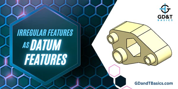
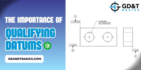
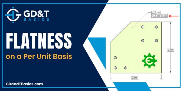
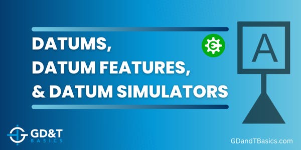
In this Question Line video, Jason explains how an irregular feature like a hexagon can serve as a primary datum feature and discusses how this part could be inspected – touching on gage design for manual inspection and point cloud analysis using a CMM.
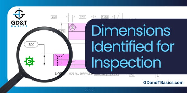
What does it mean when a dimension is circled on a drawing—and how does it impact manufacturing? In this video, Jason explains the informal use of ovals as quality control symbols and what it means for how parts are made and inspected.
In this video, Jason explains when simultaneous requirements apply and how the “separate requirements” note affects inspection, sharing examples that illustrate reasons for using each approach.
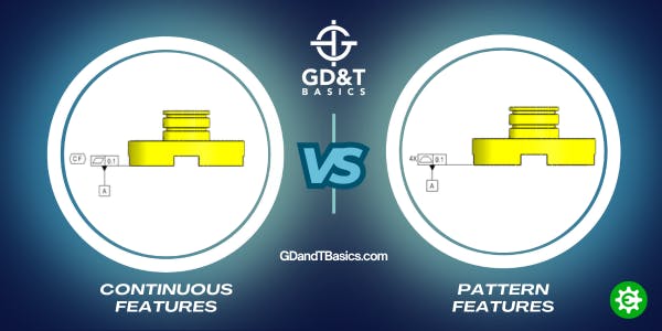
In this Question Line video, Jason compares two similar part drawings - one containing the Continuous Feature symbol and the other having a simultaneous requirement for a pattern of features - and discusses how the inspected values would be reported.
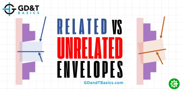
In this Question Line video, Jason explains the difference between the related and unrelated actual mating envelope and walks through an example drawing to explain when and how they are used to inspect a feature.
In this Question Line video, Jason walks through a few examples to show us the difference between profile of a surface with and without datums referenced in the feature control frame and how that affects the reported deviation.
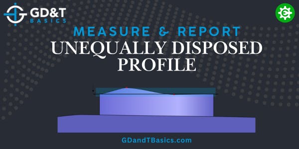
In this Question Line video, Jason discusses size dimensions to avoid with stepped surfaces and how datums and profile eliminate ambiguous dimensioning.
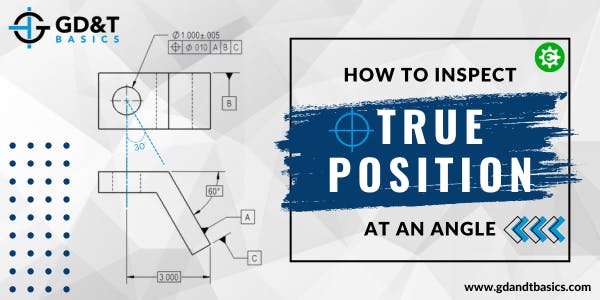
In this Question Line video, Jason answers questions regarding True Position and how to calculate diametric deviations. He discusses the difference between "True Position" and "Position" and walks through the process of determining whether the part passes inspection.
In this Question Line video, Jason reviews how Rule #1 controls the size and form of a feature of size, and what this means for ring gage design and inspection reporting.
In this Question Line video, Jason answers a question about reverse inspection of orientation and walks through an example to explain why you should not deviate from the inspection criteria given in the feature control frame.
In this Question Line video, Jason discusses manual vs CMM inspection and the reporting requirements of the ASME Y14.45 standard (Measurement Data Reporting standard).
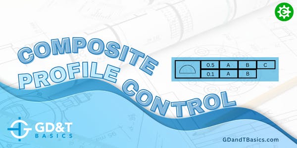
In this Question Line video, Jason discusses a composite feature control frame controlling profile tolerance. He walks through through the user submitted examples to explain the controls of each frame.
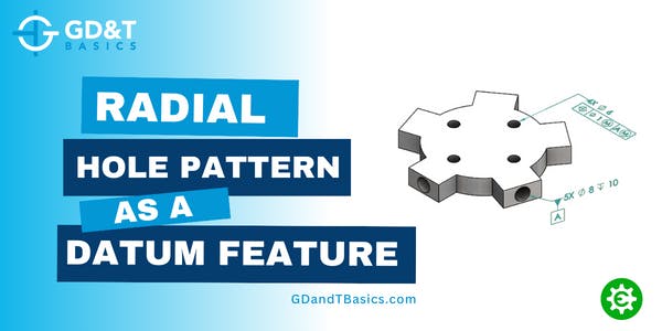
In this Question Line video, Jason responds to a question regarding radial hole patterns as datum features. He discusses how to set up the datum reference frame, how the datum reference frame controls degrees of freedom, and how to apply the Maximum Material Boundary.
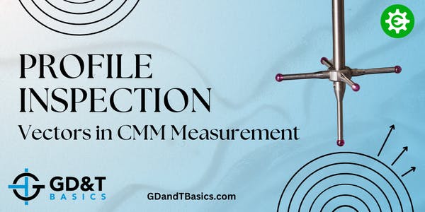
Coordinate Measuring Machines (CMMs) are essential tools for obtaining precise measurements. However, to ensure accurate measurements, it is crucial to understand how to use them correctly. In this video, Jason explains the importance of recognizing and utilizing appropriate vectors when inspecting a profile or irregular surface with a CMM probe.
In this Question Line Video, Jason uses the example of a cylindrical datum feature to show how non-planar datums can be simulated and how they are able to constrain degrees of freedom.
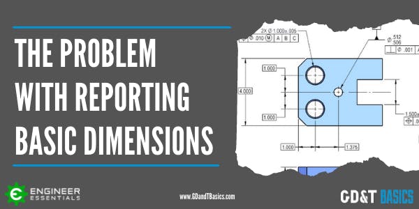
In Geometric Dimensioning and Tolerancing, Basic Dimensions are theoretically exact dimensions that define the ideal exact location and orientation of surfaces and features of size. A basic dimension is shown on a drawing as a...