
In this Question Line video, Jason responds to the following submitted question regarding the use of the LMC modifier:
Please explain the concept of the example of LMC in Figure 5-15 on page 47 of ASME Y14.5-2018 (see attached). Specifically, how does making the hole smaller, i.e., MMC, provide more position tolerance?
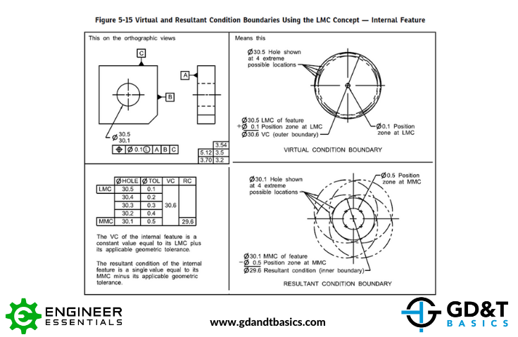
Starting with the above figure from ASME Y14.5-2018, Jason explains how the LMC modifier is applied in the feature control frame and how it relates to bonus tolerance. He then gives more clarification by discussing an example from our course of a flywheel, shown below, containing a pattern of eight holes. In this example, the holes are being controlled with a feature control frame that includes a diametric position tolerance that is modified at LMC.
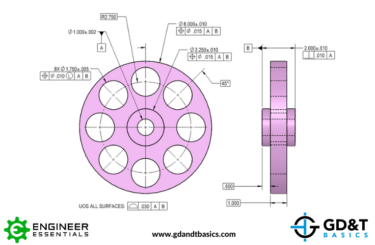
Jason walks through two different scenarios for this flywheel – one where a hole is manufactured at its LMC size and another where it is manufactured at its MMC size. He shows how the LMC modifier is used to establish a minimum wall thickness, how it affects the available position tolerance, and how improper use can unintentionally reduce the functional clearance in an assembly.
Do you have a GD&T question for us? Submit it at the link below:
https://www.gdandtbasics.com/share-your-gdt-questions/
If your question is selected, we will notify you when our video answer is posted to our YouTube channel.
* If you are a current student, reach out to us directly and we will get you into contact with your instructor. Active students’ questions receive a direct response within 24-48 hours.
Stop hunting through pages. Get our GD&T Symbols Chart—your quick reference guide with every symbol on one page.
Save it to your desktop or print it out for quick reference. We’ll send the digital chart straight to your inbox. No spam, just helpful GD&T resources.
Get Your Free Chart