
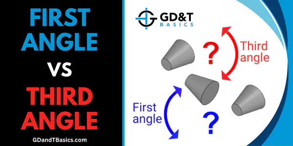
Three-dimensional parts are represented in two dimensions on engineering drawings using orthographic views. These views show the object from different directions and are arranged on the drawing using either first angle or third angle projection. Correctly identifying which projection method is being used is critical, as misinterpreting this can lead to costly manufacturing errors and incorrectly produced parts.
In this video, Steve explains how to recognize the 1st angle and 3rd angle projection symbols found in the drawing title block. By rotating 3D models, he demonstrates how each projection method translates into its corresponding 2D views.
For more information on First and Third Angle projection, see:
How Does 1st Angle Projection Work?
First vs Third Angle – Orthographic Views
Looking for a handy chart to help you with orthographic views?
Download our FREE orthographic views wall chart today.
Download Free Wall Chart