Using GD&T Position to control the location of a feature of size allows 57% more positional tolerance than when using coordinate dimensions.
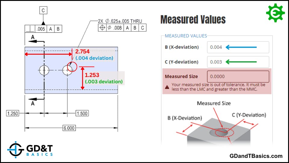
This increase is due to the shape of the tolerance zone. While coordinate dimensions result in a rectangular tolerance zone, the tolerance zone for GD&T Position is diametric. When inspecting the location of the feature, the method of inspection is the same – you still measure deviation in the X and Y directions. However, these X and Y deviation measurements must be converted into a single diametric deviation value.
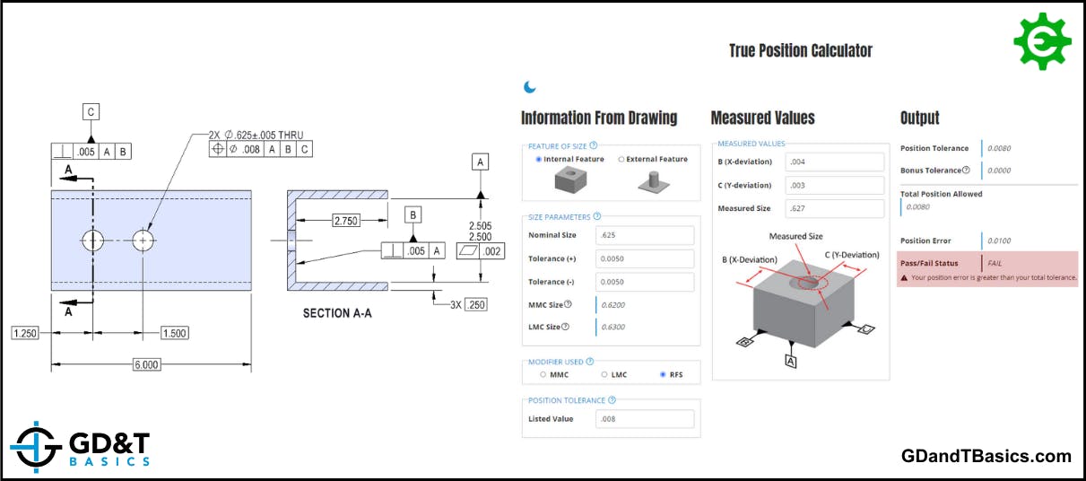
We have created a handy calculator to do this conversion for you!
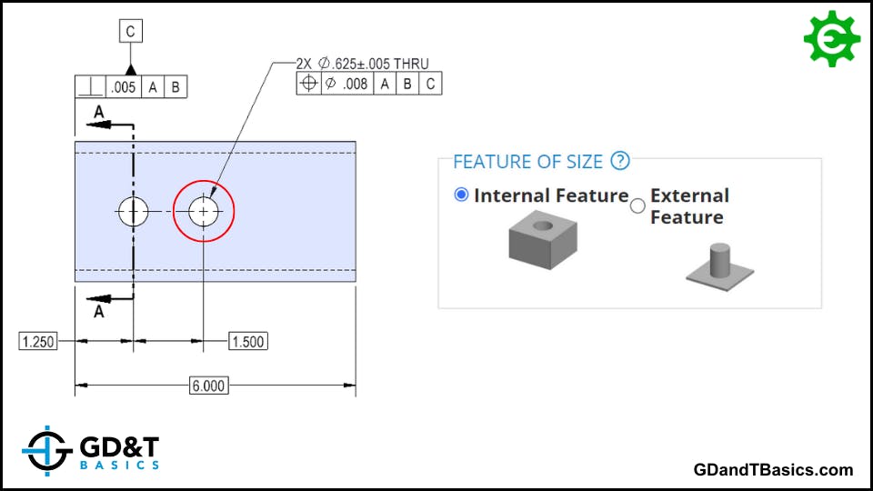
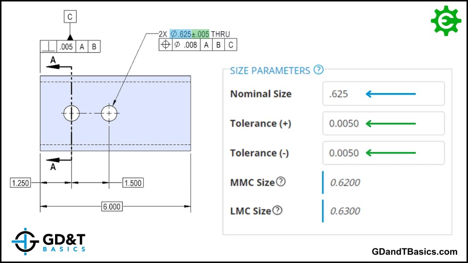
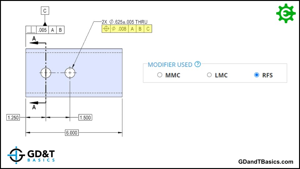
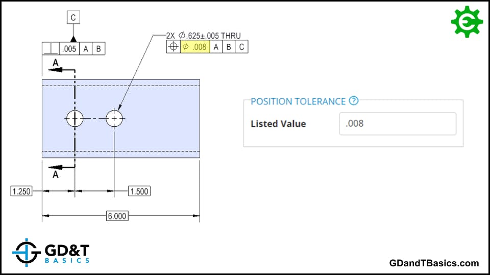
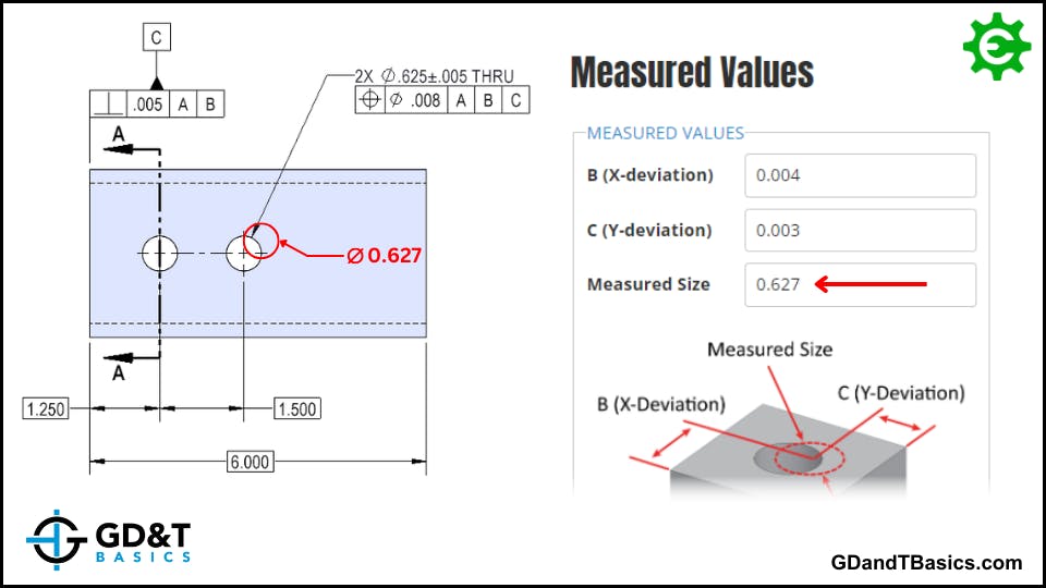
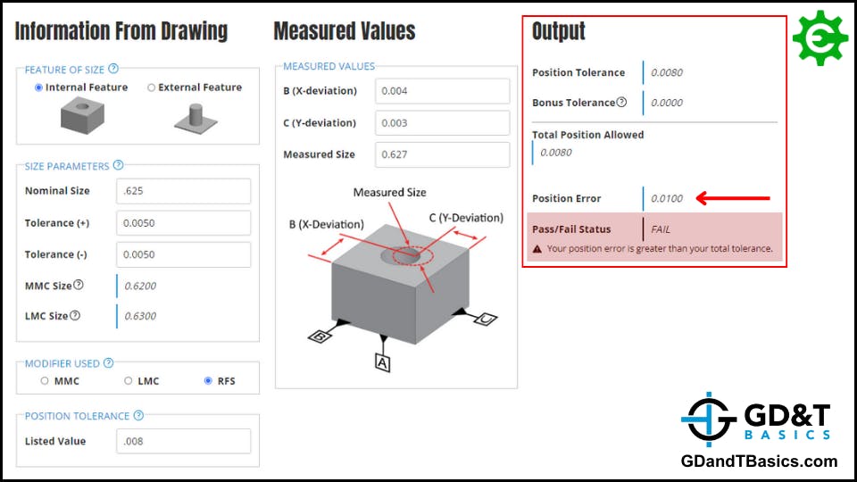
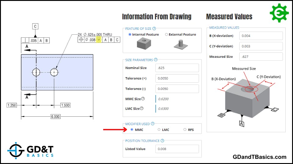
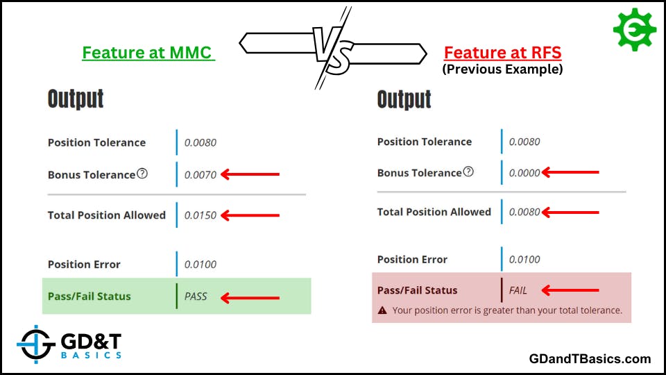
To use the calculator, enter the information from your drawing and input the measured values for your feature. The calculator will then output the total position tolerance, including any potential bonus tolerance, the calculated position error (diametric deviation value), and indicate whether your feature meets the drawing requirements for position. Below the calculator, you will find step-by-step examples of how to enter the information and the results to expect.
**In search of a comprehensive explanation of why position is the preferred choice over coordinate dimensions? Click here to learn more!**