
Chamfers, rounds, fillets, and “break edges” are edge features that you may commonly see on your part drawings. They are used for a variety of reasons, which typically include: part strength, burr removal, ease of assembly, and aesthetics.
Chamfer Definition:
A chamfer is an angled cut on the edge of a part. Chamfers can be used on an internal or external edge. In Figure 1, a chamfer is shown on the edge of a hole feature.
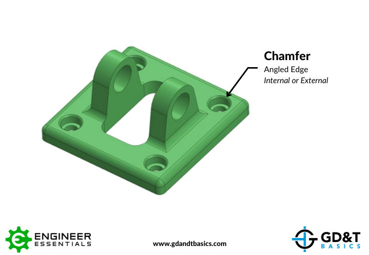
Figure 1: Part with a Chamfered Edge
Application:
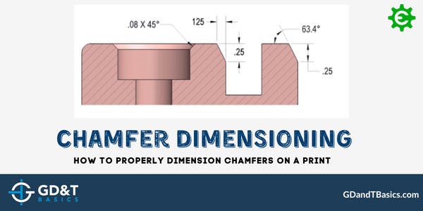
Chamfers can be dimensioned in two ways, either by calling out the length by angle, or calling out the length by length. If an angle other than 45 degrees is dimensioned, the surface to which the angle is measured must be made clear on the drawing. See Figure 2 for chamfer dimensioning examples.
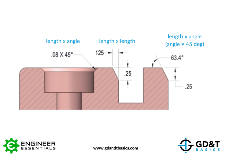
Figure 2: Chamfer Dimensioning
Learn more about chamfer dimensioning in the video below:
The one-page GD&T reference that you will use every day
A visual breakdown of every core GD&T symbol and what it controls, all on one page. Bookmark it. Print it. Actually use it.
Download the Chart