
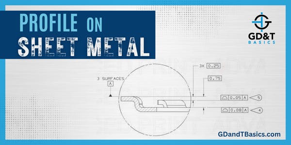
In this Question Line video, Jason answers the following question regarding profile on sheet metal:
This (part) is tooling controlled and made of steel so the material naturally wants to go back to flat, so theses forms will never be in a true position 1000% of the time. So how do I report this and is this a dimension the customer should be putting a tolerance on? I believe the reason for the boxed dimensions are that the height of these forms is fairly critical to their process.
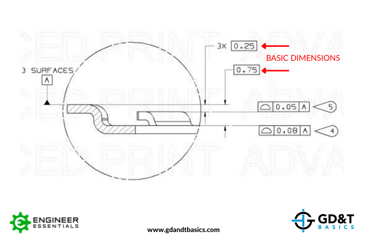
Jason reviews the above submitted drawing, which shows three surfaces establishing Datum Feature A. Two other faces are controlled with a profile of a surface tolerance with respect to Datum A, and their positions are defined by basic (boxed) dimensions. He explains that these basic dimensions do not carry tolerances—they indicate the target location for centering the profile tolerance zone. Jason then walks through how the part would be set up for datum simulation and inspection.
Got a GD&T problem you can’t crack? Send it to our team using the link below.
https://www.gdandtbasics.com/share-your-gdt-questions/
If your question is selected, we will notify you when our video answer is posted to our YouTube channel.
* If you are a current student, reach out to us directly and we will get you into contact with your instructor. Active students’ questions receive a direct response within 24-48 hours.
The one-page GD&T reference that you will use every day
A visual breakdown of every core GD&T symbol and what it controls, all on one page. Bookmark it. Print it. Actually use it.
Download the Chart