

In this video, Brandon discusses basic dimensions and why they should not be recorded on an inspection report.
What Are Basic Dimensions?
Basic dimensions are used in Geometric Dimensioning and Tolerancing to describe the theoretically exact location, orientation, size, or profile of a feature or datum target. Because basic dimensions are theoretically perfect dimensions, there are no tolerances associated with them. A basic dimension is noted as a dimension with a box around it and must mathematically relate back to the Datum Features. In ISO standards, basic dimensions are called TEDs – Theoretically Exact Dimensions.
Because basic dimensions refer to theoretically perfect positions, when chain dimensioning basic dimensions, there is no tolerance accumulation.
Basic dimensions must always include a geometric control to ensure that there are no dimensions with a zero tolerance. Therefore, a basic dimension can be thought of as a nominal dimension where the geometric tolerance sets the tolerance range. Basic dimensions are always used to locate a feature using Position.
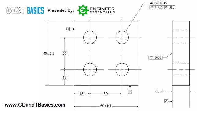
To better understand basic dimensions, let’s look at an example. Figure 1, which is discussed in the video, shows a part containing a pattern of four cylindrical holes. Basic dimensions of 15 and 30 are used to locate the true position of the holes from Datum Features B and C. We know that these are basic (thus, perfect) dimensions because this is indicated by the dimensions having a box around them. The geometric tolerance for the holes, shown in the feature control frame at the upper right hand of the drawing, defines the tolerances for both the position and size for the pattern of holes.
Should Basic Dimensions Be Recorded on an Inspection Report?
Dean asked us the following question regarding basic dimensions and inspection reports:
“When performing FAI (First Article Inspection) for basic dimensions, should actual values be reported, or should we just report the basic dimension value? I am hesitant to report actual values for basic dimensions as the tolerances are already measured in other callouts.”
In answer to this question:
Basic dimensions are used to locate True Positions. There is no tolerance or deviation in the basic dimensions themselves, as they are theoretically perfect. The tolerance zone for the feature comes through the geometric tolerance shown in the feature control frame for that feature.
If we were to make an inspection plan for the part shown in Figure 1, we would report deviations. The basic dimensions in this example locate the perfect position of the tolerance zone and cannot change. As basic dimensions are perfect, there would be no deviations, and they would not be recorded on the report.
Instead of basic dimensions, we would report the following:
- Flatness for Datum A
- Size of the part (60 +/- 0.1 for length and width)
- Thickness of the part (16 +/- 0.1)
- Size of the holes (Ø12 +/- 0.05)
- Position of the holes (cylindrical tolerance zone of Ø0.1)
Summary
Basic dimensions are theoretically perfect dimensions; therefore, there are no tolerances associated with them. They work together with the geometric tolerance of a feature. The basic dimension sets the perfect position of the tolerance zone of a feature, while the Geometric tolerance defines the tolerance zone size and shape. Because there is no deviation in a basic dimension, basic dimensions will not be recorded on an inspection report.
Interested in learning more about GD&T?
Check out the GD&T Basics Fundamentals course!
Click here for information