

Jason answers the following question regarding which takes precedence – CAD model or drawing information – in this Question Line video:
General note states: “break all sharp edges .020 max.” Customer’s supplied model has .050” radius on all corners. Notes supersede dimensions even if the model has a radius. The note states “ALL”, which includes every corner. What would be the rules here?
The submitted question involves a drawing that says to break all sharp edges to a certain limit, while the customer’s CAD model shows a larger radius on every corner. Jason walks through how to approach situations like this—starting with any internal documentation or customer agreements that may override the usual ASME rules, and then moving into what the standards say when no special agreement exists.
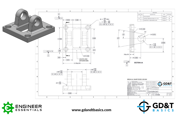
Using a clevis bracket drawing, he breaks down how precedence works inside the drawing itself (what’s shown in the field of view versus what’s written in the notes or title block) and how that compares to the information in the CAD model. Jason also stresses the importance of having a conversation with the designer when something doesn’t seem to line up, so the original intent is understood before manufacturing moves forward.
Looking for answers to your GD&T questions? Submit your question to our GD&T experts at the link below!
https://www.gdandtbasics.com/share-your-gdt-questions/
If your question is selected, we will notify you when our video answer is posted to our YouTube channel.
* If you are a current student, reach out to us directly and we will get you into contact with your instructor. Active students’ questions receive a direct response within 24-48 hours.
Stop hunting through pages. Get our GD&T Symbols Chart—your quick reference guide with every symbol on one page.
Save it to your desktop or print it out for quick reference. We’ll send the digital chart straight to your inbox. No spam, just helpful GD&T resources.
Get Your Free Chart