
GD&T Symbol: 
Definition:
True Position, or just Position as the ASME Y14.5 standard calls it, is defined as the total permissible variation that a feature can have from its “true” position. The “True Position” is the exact coordinate, or location defined by basic dimensions or other means that represents the nominal value. In other words, the Geometric Dimensioning and Tolerancing “Position” tolerance is how far your feature’s location can vary from its “True Position”.
Position is one of the most useful and most complex of all the symbols in GD&T. The two methods of using Position discussed on this page will be RFS or Regardless of Feature Size and under a material condition (Maximum Material Condition or Least Material Condition). However, since this is such a useful symbol, we will continue to add content and examples for other uses of this nifty little symbol in the coming months.
Application:
Although incorrect, we title this page and sometimes refer to the symbol as “True Position” since this is typically the term people are referencing when they are looking for the position tolerance. However, it is correctly termed in the ASME Y14.5 standard as simply “Position”. For clarity on these two terms check out our article and video here.

Position may be applied to any feature of size (Feature with physical dimensions like a hole, slot, boss, tab, or sphere) and control the central elements of these size features. See the above central elements of a hole, slot and sphere. Locating surfaces is to be controlled via Profile. Position can be used with Max Material Condition (MMC), Least Material Condition (LMC), projected tolerances, and tangent planes.
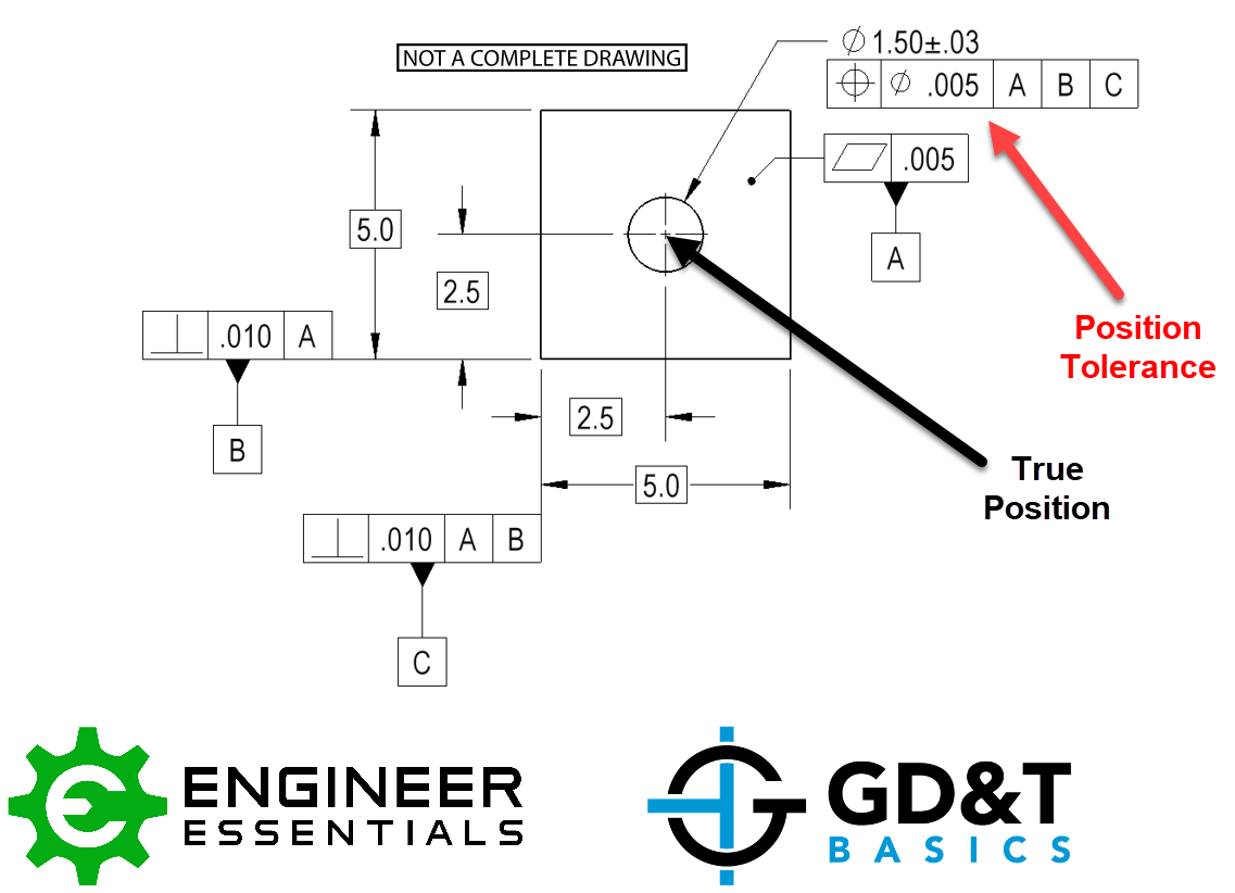
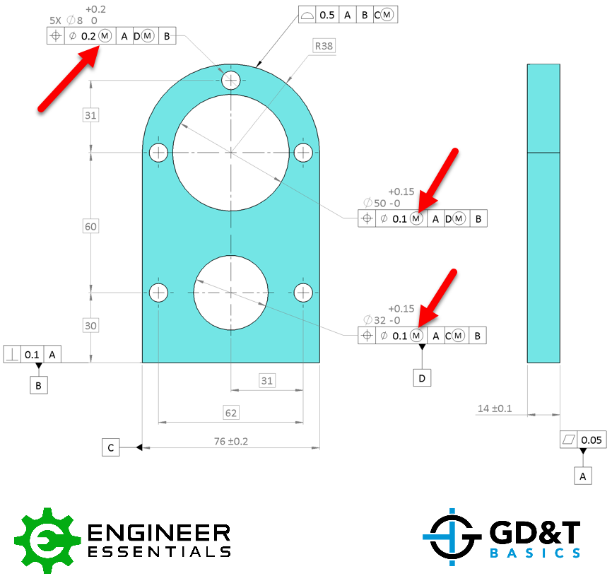
In the image below you can see how a hole is called out using the position tolerance symbol. However, this can also be applied to any feature of size in need of a location tolerance, such as a pin, a boss, or even a keyway. When you have a hole in a part such as a bolt pattern, true position is usually called out. It can be used almost anywhere to represent any feature of size.
Position in terms of the axis, point, or plane defines how much variation a feature can have from a specified exact true location. Again, True Position is the exact perfect location of the feature, located and oriented to the datum reference frame using Basic Dimensions.
Position Tolerance Zone
The tolerance is a 3-Dimensional tolerance zone that surrounds the true position. When specifying a position tolerance, datum features are referenced within the feature control frame. This means that you will have an exact point where the position should be with respect to a datum reference frame and your tolerance specifies how far from this you can be. The position is most often referenced with two or three datum features to exactly locate and orient the true position. If the feature of size is a cylindrical feature such as a hole in a part, the size value in the feature control frame is preceded by a diametric symbol to represent a circular or cylindrical tolerance zone.
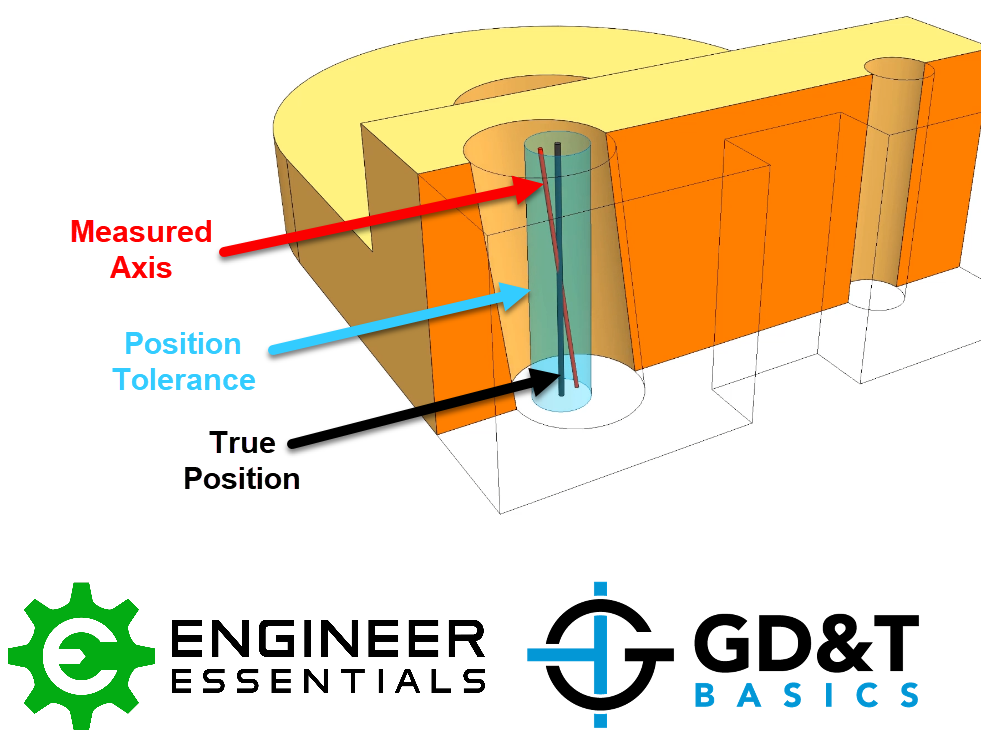
The cylindrical tolerance zone would extend though the thickness of the part if this is a hole. The entire features axis, midplane or point would need to be located within this tolerance zone.
To measure or inspect the feature regarding the position control, X and Y measurements can be taken of the feature with respect to the datum features called out in the feature control frame. These measurements can quickly be converted to a total diametric deviation. If your diametric deviation is less than the specified tolerance, the feature passes. Remember, in order to capture orientation deviations, multiple measurements will need to be taken along the “depth” of the hole or feature.
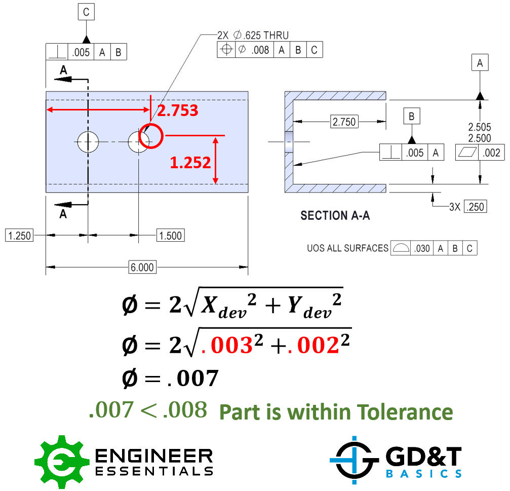
For the example above, the hole is measured to be off by .003” in X and .002” in Y. Using the shown formula, the diametric deviation is calculated to be .007”. The stated positional tolerance is .008” so the part is with in spec and can be passed.
Position using material condition modifier (MMC/LMC)
The position of a feature of size with MMC is used when a functional gage is ideal for checking the part, typically this is used when a clearance fit is utilized with some sort of fastener.
If you specify the control using MMC, it allows the locational tolerance to be dependent on the size of the feature. You will see position called with MMC very commonly in clearance bolt patterns where location of all the bolts is dependent on the size of the clearance hole. LMC with position is a little less common but often used when controlling a minimum wall thickness is desired.
Position used with Maximum Material Condition becomes a very useful control. Position when paired with the size tolerance of that feature can control the location, orientation, form, and the size of the feature all at once. MMC position is helpful for creating functional gages that can be used to quickly insert into the part see if everything is within spec. While the position tolerance on its own controls how far from true position the feature can be regardless of the size of the feature, position in conjunction with MMC sets a minimum size and positional location of the hole to maintain functional control. It allows the position of the part to be dependent on the feature’s actual size. It does this by allowing a bonus tolerance to be added to the part. As a part gets closer to the MMC, the constraints become tighter, and the hole must be closer to its position. But, if the hole is a bit larger (but still in spec), it can stray from its true position further and still allow proper function (like a bolt passing through).
The tolerance zone is the same as above, a 3-Dimensional cylinder, centered at the true position location referenced by the datum surfaces. The cylindrical tolerance zone would extend through the thickness of the part and would vary in diameter depending on how much bonus tolerance is allowed with respect to the features actual size.
Bonus Round
When a functional gage is used for Position, any difference the actual feature size is from the maximum material condition would be a bonus tolerance. The bonus tolerance for position then increases as the part gets closer to LMC. The goal of a maximum material condition callout is to ensure that when the part is in its worst tolerances, the Position and Size of the hole/pin will always assemble. For instance, if you had a large hole size but were still in tolerance (closer to LMC), you make more bonus tolerance for yourself making the position tolerance larger. You can now have the hole center more out of position due to the bonus tolerance.
Bonus tolerance = (measured hole size – MMC hole size)
Note: Keep in mind the opposite is true for a positive feature like a pin, where the smaller the pin means you have more bonus tolerance.

When a part is checked for position under a feature of size specification, usually a functional gage is used to ensure that the entire feature envelope is within specification. Essentially it is simulating the worst-case scenario boundary of mating parts. If you have a specification for Maximum Material Condition, the desired state is that the surface of the feature will not cross a functional envelope known as the virtual condition. For MMC on a hole this usually means a boundary of the “worst case scenario” that still allows assembly. The following formulas are used to create a gage for position under MMC.
Fixed Gaging of an Internal Feature
For the true position under MMC of a hole:
Gage Ø (pin gage) =Min Ø of hole (MMC)-True Position Tolerance
Fixed Gaging of an External Feature
For position under MMC of a pin:
Gage Ø (hole gage) = Max Ø of pin (MMC) + True Position Tolerance
Locations of the gage pins or holes are given on the drawing as basic dimensions. All gage features should be located at the true positions but sized according to the formulas above.
Remember the further you are from MMC when it is referenced in the feature control frame, the more bonus tolerance you are allowed. For a hole, the larger the diameter, (closer to the LMC) the more bonus tolerance you have for your true position.
Called with or without the Ø symbol
There are two ways position can be called out – either as a distance, in X and Y or most commonly as a diameter. When position is called out as a distance, you are permitted to move from the tolerance in X or Y direction by the allowed tolerance. However, when done this way, the tolerance zone forms a square. This is usually undesirable since in the corners of the square are further from the center than the sides. This also removed over 57% of your tolerance zone! Most commonly, position with reference to location is called with the diameter (Ø) symbol to be called as a cylindrical or circular tolerance zone.
Confused? No worries! For more detail on how bonus tolerances play into these callouts, see our sections on Maximum Material Condition. Or check out our GD&T Course, where we go into deep detail on the position symbol!
Relation to Other GD&T Symbols:
The position symbol is the locating symbol for Geometric Dimensioning and Tolerancing. It locates features of size while also controlling orientation. Paired with the size tolerance of that feature, they control Size, Location, Orientation and Form. It cannot however control the location of surfaces, which is where profile of a surface steps in. It acts much like position does however it can control the Location Orientation and Form of the elements of a surface.
True position controls orientation which means it already controls a feature in the same way as Perpendicularity, Parallelism and Angularity can. The tolerance of both position and these orientation controls refer to a cylindrical envelope of a central axis. However, with true position you can make the tolerance referenced to several datum’s as opposed to just one with axis perpendicularity thus controlling the location as well. When you callout true position using datums on the face, and sides of the part – perpendicularity is controlled as well.
Special Notes:
Here is a sample lesson from our GD&T Basics Fundamentals Course. We explain why it is much better to use a Position tolerance and Basic Dimensions over locating your feature with a coordinate dimension system.
Position is probably the most widely used symbol in GD&T. If you are looking for more information about Position or any of the other symbols, you should check out our GD&T Fundamentals Course. If you like the simplified approach to GD&T on this website and in the video above, be sure to contact us to learn more about the course!
Be The Go-To Engineer at Your Company
Learn GD&T at your own pace and apply it with confidence in the real world.
Get GD&T TrainingAll Symbols


it is a great website. before reading from there i was friendly with the position tolerance, but now feel more confident….thanks a lot
Hi, sorry if this has been addressed in the comments already but I’m having trouble understanding composite tolerances and how they impact position callouts with one datum.
For ex I have a composite position callout for 3 holes with the top row being |tp symbol | diam .003 |A B C|, and then the bottom in a separate box |tp symbol|diam .001|A|. From what I have read the idea of the bottom row (whether the tp symbol encompasses the entire block or is 2 separate lines) is to define the location of the hole pattern, and to do that you would set one of the holes as origin and calculate position as normal from there for the remaining holes.
However I’ve also been told that if you only have one datum that is perpendicular to the holes in question in the lower callout, then what they are really asking for isn’t position but perpendicularity. Is that correct? Thanks for the help.
James –
You have the general idea. Be careful that when you have the position symbol called out ONCE you have a composite feature control frame. The upper segment is referred to as the Pattern Locating Tolerance Zone Framework (PLTZF or Plahtz) and the lower segment is referred to as the Feature Relating Tolerance Zone Framework (FRTZF or Fritz). The upper segment serves as a regular feature control frame that you are used to. The lower segment depending on how many and what datums are called out serves to refine and further restrict the orientation of your pattern with respect to datum reference system. In the case that you bring up, if only the primary datum A (I’m assuming that it’s a flat surface for this example) is called out then all you are doing is indeed restricting the perpendicularity of the features. The smaller tol zone of the Fritz is free to move within the tol zone of the Plahtz in any orientation or translation. One key point to remember is that the basic dimensions between your features STILL holds true.
I hope this helps with clarity. I also hope that you take advantage of some of the fantastic course options we have available.
Cheers,
Matt
Hi,
I regularly see drawings where spacing between a pair of holes is critical but not so much the position of the pair as a whole. Often the dimension to the first hole is sheet tolerance and then the spacing between them is basic with a true position indicating the allowable deviation. I don’t believe this to be correct as your first hole is still subject to the looser tolerance and you are not positioning your second hole from the centre of where the first hole falls but by the dimensions stated. Is my understanding of this right?
Ash –
Your understanding is correct. The example you bring up is a great one for use of a Composite Feature Control Frame. Position used with a composite feature control frame is akin to saying I’m less concerned with where on the wall I hang the painting than I am with fact that it’s 6′ off the ground and level.
As you have described the drawing, the way that they have the control called out is wrong. You can’t use drawing tolerances to locate to a feature that you then try to control with a feature control frame. I believe that this is due to a fundamental lack of understanding of GD&T. Using GD&T, ALL of your tolerance comes from the value in the feature control frame and actually for the same tolerance value between traditional and GD&T you get 57% more with GD&T than you do with drawing tolerances. I’ll prove it to you, draw a square of any size, then draw a circle around it so that the corners of the square touch the circle. If you imagine the center of the circle as the desired location of your feature and the sides of the square as your traditional drawing tolerance you’ll notice that there is a region between the circle and the square that is not available for use with a standard +/- tolerance. If you do the math you’ll see that you get 57% more using a circular tolerance zone.
Back to your specific question. To simplify things I’m going to describe two holes on a flat rectangular plate. Size and actual location of the features doesn’t really matter. Datum A is the surface you are going to be drilling into, you want it to be nice and flat because you want your holes to be perpendicular to it. Datum B is the bottom edge of the plate, Datum C is the left edge of the plate. What you would do is then use basic dimensions in X and Y to define the position of both holes relative to the intersections of Datums A, B and C (this would be the lower left hand corner of the plate).
Now, since you said you don’t really care about the location of the PATTERN, you could build a composite feature control frame for position with a tolerance of 1 inch for the upper segment if you want. You’re saying that within a 1 inch diameter circle I want the first hole drilled. Now, add another feature control frame below the first but with a tolerance of .036. This says that the actual axis of the first hole must be located within the a diameter of .036 and that there can only be .036 worth of offset in the distance between the holes. In general the smaller tolerance zone of .036 is free to float, rotate and translate within the 1″ tolerance zone. However, depending on what datums you have called out may restrict how the smaller zone may rotate.
I sincerely hope this helps your understanding of how position and composite feature control frames work. I encourage you to keep coming back to ask questions and that you take advantage of our great lessons at GD&T Basics. It sounds as though our onsite training may be of use to your business.
Cheers,
Matt
Hello,
Is it best to put a form tolerance on datum’s? So A and B here.. say a flatness?
If this is the case do you incorporate the flatness in a tolerance stack for calculating hole position.
Cheers,
Liam
Liam –
Yes, it is a very good idea to qualify your datums, so to speak, by applying form and orientation controls in particular. For my example I’m going to use a flat rectangular plate with holes in it. Assuming that your broad flat surface is your primary datum it is best practice to include a flatness tolerance. Further, it is generally advisable to apply a perpendicularity tolerance to datum B relative to A and then another one to C relative to A and B. This provides stability for the part in the inspection equipment as well as limits some unique tolerance stacking issues that can come about.
We actually address this very issue in one of our GD&T Advanced Lessons. I strongly urge you to consider signing up for the course at GD&T Basics.
Hope this helps clarify your understanding of the situation.
Cheers,
Matt
Does Pitch circle diameter has tolerance while defining the position of the hole??
No – the pitch circle should have basic dimensions as the only tolerance is contained within the position itself.
Doe the pin Gage is machined with same position tolerance or at worst case of position tolerances?
Mohammad –
The rule of thumb from ASME Y14.43 is 10% or less of the feature tolerance should be used for the gage tolerance. I strongly encourage you to reference the spec I mentioned. We also address functional gage design in one of our lessons in our GD&T Basics – Advanced Course.
I hope this helps, cheers.
Matt
Shall we provide the positional tolerance with diameter symbol?
Deepak –
It depends, is what you’re trying to control a cylindrical feature of size (internal or external)? If it is, then yes. Otherwise no. Consider taking our GD&T Basics course. Plenty to learn.
Matt
Does true position of a cylinder refer to the location of a single point on the axis or the entire axis. If it is the entire axis how would you calculate it. I’ve always seen TP as a two dimensional control but we have a blueprint with TP called out on a diagonal hole and I don’t think our CMM is computing it correctly.
Richard –
I can’t help you with the CMM, but I can help clarify your understanding of position. The tolerance zone applies to the entire axis along the entire thickness of the feature. For a cylindrical feature you are defining a tolerance zone of x diameter relative to datums A, B, C etc. The entire axis of the cylinder must lie entirely within this tolerance zone for the part to be considered acceptable. This includes the combined effects of translation (x, y translation) and orientation (feature tilt). Additionally, ever two point measurement of the feature must be within size for the part to be correct.
I hope this clarifies things. If now, feel free to come back and ask additional questions.
Cheers,
Matt
what is the differece if a postion have Diameter symbol and don’t have have a diameter symbol and how its affects the position
Ramesh –
This is a quick an easy one. If the diameter symbol is present then it indicates that the tolerance zone is a diameter and the control is applied to a cylindrical feature of size (like a hole). If the symbol is absent then the tolerance zone is the space between two parallel planes and the control is applied to a non-circular feature of size (like a tab or slot).
Hope this helps. We have excellent content that goes over topics like this and many more in our GD&T Basics – Fundamentals Course. It’s an in depth self paced course that many of our customers have found to be immensely helpful.
Cheers,
Matt
True position on the drawing doesn’t have any datums. What does it mean?
Oleg –
Typically, in the vast majority of instances a position control always requires the use of at least one datum. The only exception to this rule is if the drawing is trying to control the co-axial relationship between two separated diameters. Think of a wooden rolling pin, like you might find in the kitchen. If you wanted to ensure that the two handles of the pin were maintained, within a certain degree, were aligned on the same axis you could specify a positional tolerance with no datums. This is somewhat of a more rare circumstance, but it does come up. The only place it’s mentioned is in the ASME Y14.5 – 2009 spec in Figure 7-59.
If your situation is anything different than what I’ve described then your drawing is in error and needs further refinement. Come back and contribute further to the community knowledge base.
We cover this topic and many others in our GD&T Advanced Course. Visit our website course listings for additional information.
Cheers,
Matt
Can you explain to me, what is the function of 2 on formula of comparison between true position an actual position (in X and Y)?
Kristiono –
If I understand your question correctly you’re wondering why we are multiplying the term under the square root for determining actual position based off of measurements by 2? The reason is that the positional tolerance is diametral (i.e. a diameter) vs a radius.
Hope this clears things up.
Cheers,
Matt
Can you have a true position callout to only one datum?
Charles –
Yes, this is perfectly legal. In this manner the position control is typically serving only as a perpendicularity control. Classic example of multiple ways to accomplish the same thing. I prefer to be direct however, if you intend on the position control acting only for perpendicularity then use the perpendicular control. Another possible scenario is with a circular pattern and you don’t care about perpendicularity. Imagine a flywheel, the broad flat face could be a datum and the outer diameter is another. For your application you may want to control the centerline drive hole only by location to the outer diameter and not the flat face. The control would be legal. Conversely, you could only reference the broad flat face and effectively say you don’t care about location. I’m not suggesting you do either, just that the call out is permissible.
I hope this clarifies a thing or two. Thanks for checking in with us.
Cheers,
Matt
If one of two Datum is Cuver Surface so Can I using GD&T for evaluate the True position ?
Van –
I’m not sure I understand what you are asking. Can you elaborate?
Matt
Great post, the visuals helped out a lot. Thanks!
Good day, what is least tolerance for a true position between 2 holes on a “C” -shaped stamped part.
Regards
Sergio –
I’d like to help, but I need more information regarding the nature of your question. Drop in and we’ll see what we can do to help you out.
Cheers,
Matt
Is there a formula to calculate error in position using polar radius and polar angle without converting to a carteseasn coordinate system first? i’m trying to check the math on my CMM machine and can’t get the numbers to jive up
Patrick –
Not that I’m aware of. You might find some white paper from an engineer or master’s student that does just that, but I can’t think of anything off the top of my head that is going to be of immediate use to you. Sorry about that.
Good luck and let us know if you come across anything.
Cheers,
Matt
Ok, this may seem like a silly question. I have a true position callout, TP[0.5|X|Y|Z]. There is no diametric call out with the tolerance. We send the parts to be measured by CMM with a third party. The report the gave us shows the true position OOT, measuring 1.322, (TP RFS 1.322). The only way I can replicate this result is to either calculate TP with X and Z coordinates and use diameter position tolerance, or spherical diameter true position with all X, Y, and Z. Mind you, I am rather lost in all of this and the nomenclature, but I can make the math work. My question is, is that the correct way to do it? The drawing does not call out the diameter symbol in the FCF. The feature being measured is a square hole dimensioned at 9mm by 9mm with a +/- 0.3mm. There is also no call out for MMC or LMC. Actual coordinates measure at X (-248.615), Y (736.919) and Z (425.989). The drawing shows coordinates to be X (-249.060), Y (736.920) and Z (452.500). Please help me as I am so very confused.
Emily –
The diameter symbol is only required if you are trying to control a cylindrical feature. In your specific case, the location of the center plane as defined by the edges of the square hole, is what is being controlled. Further, because neither MMC or LMC is called out there is no ‘bonus’ tolerance permissible. You only get a tolerance equal to what is stated in the feature control frame.
I would read your feature control frame as follows. The mid-plane of the controlled feature is restricted by a tolerance zone of 0.5 width, likely oriented to datum X and located to datums Y and Z.
I’m taking a few guesses here as I don’t obviously have your print in front of me. The mid-plane of your feature should be located with basic dimensions back to the intersection of datums X, Y and Z. This theoretical, exact location is where I am stating I want the mid-plane of my feature to be. This is called the True Position. Now, I understand that there are imperfections in manufacturing and I am allowing this mid-plane to vary in both orientation and location by the size of my tolerance zone. This tolerance zone is also centered about the True Position and is defined by two parallel planes 0.5 apart. These planes are oriented, that is perfectly perpendicular, to datum X (I’m guessing) with a center located from datums Y and Z.
I sincerely hope this helps your understanding. This is a lot to pack into a forum response, but I encourage you to take a look at our GD&T Basics course. All of this and more is covered in our course and can help out in your understanding of the situation.
I hope this helps,
Cheers,
Matt
Hi Matt,
I have one question. In drawings sometimes there are two datums, three datums and one datum why?
Maruti –
It all depends on what you are trying to control. The simplest example would be of a parallelism call-out. Your feature control frame would call out the control, the tolerance and a single datum as follows. |//|.020|A| You are in effect stating that you want the indicated surface parallel to datum A within a tolerance zone of .020.
In another example you have a rectangular plate. 1 broad flat face is datum A, the long edge is datum B and the short edge is datum C. Now, you wish to control the perpendicularity of datum C relative to datums A and B. Your feature control frame would be |perp|.010|A|B|. This feature control frame is stating that the surface C needs to be within a tolerance zone of .010. Keep in mind that this zone has to be theoretically exact in it’s perpendicularity to datums A and B.
In the third and final example you wish to locate a hole on a flat rectangular plate. 1 broad flat face is datum A, the long edge is datum B and the short edge is datum C. Your feature control frame might like this |pos|dia .020|A|B|C|. With this control you are saying that the tolerance zone that the axis of the hole must lie in is .020 in diameter and is theoretically exact in it’s perpendicularity to datum A. Since datums B and C are called out, the center of the hole is basically located a distance from datums B and C.
I hope this is making sense. If not feel free to ask additional questions.
Cheers,
Matt
So here is a question.
Say I have a cylindrical part with a hole that runs through the cylinder (i.e. through the circular faces). The position of this hole needs to be concentric within some level to the circular boss. So this boss is being used as the datum This hole is a clearance hole to allow a shaft to pass through. Which is the best GD&T to use in order to properly tolerance this hole?
-Concentricity could work, but it is difficult to measure and there is no bonus tolerance.
-True Position could also work, but if you do the math the bonus tolerance zone increases by half the diametric deviation from MMC instead of the full. (everything Ive done has said this at least.
-runnout has the same issues as concentricity, although easier to measure.
I want the bonus tolerance of true position, but the tolerance zone expands twice as fast as I want it to. Maybe Im overthinking it.
Ryan –
I believe that you can accomplish what you are trying to do with position. I’ll make some assumptions here, but this is one way of doing it. Label the inner bore as datum A, and one flat end of the boss as datum B. I’m assuming the two are perpendicular to one another. Datum A has defined an axis and Datum B has defined a plane. You can locate your through hole on the diameter of the cylinder. By using position and calling out datum A primary and datum B secondary you are stating that the tolerance zone is located theoretically perfectly wherever datum axis A exists and located exactly some distance from wherever datum B exists. Since you have a thru hole you’re concerned about the coaxiality of the two holes. One way of controlling this by using a composite positional tolerance. You can use the upper segment of the control to locate the feature and the lower segment of the control to dictate the coaxiality. Keep in mind that lower segments of composite controls only restrict the orientation of the tolerance zone and not the location.
There are multiple ways of doing what I think you want. I would recommend taking a look at section 7 of the ASME Y14.5 – 2009 standard. There are multiple examples of controlling coaxiality.
Finally, come back and let us know what you finally decide on for your solution. Help expand the community knowledge base. I hope this helps.
Cheers,
Matt
In your description of this symbol, you mentioned that “position can be used on any feature”. Can it be used on a planar feature? In the standard, i have only seen this applied on a feature of size.
Sam –
You are correct. It is not able to be used on a single planar feature. Its use is restricted to features of size. We will clarify this now to make sure people understand it is only used on a feature of size.
Cheers,
Matt
Matt,
I learned a lot from your excellent website and it is my pleasure to be helpful even if it’s just a small thing.
If we reverse this example and it’s actually a plate with 10.0 diameter pins that is the part, would the GD&T frame be the same? And if we made a gage to check the part, would it then have holes that are 10.3 diameter?
Hello, is the Positional tolerance able to control also the position in Z-axis? Let me make this practival example: I have a hole diam. 10 with TP diam.2 (MMC) to ABC. If on the part the hole is located perfectly w/respect to B and C but is 5mm away from datum A (where in theory it should lie on) is a Not-ok part or not?
In other words, the tolerance diam.2(MMC) ABC is descriving a cylinder where the actual axis must be found, but how tall is such cylinder?
Thank you in advance for your clarification
Andrea
Andrea –
Datum A is orienting the tolerance zone (cylinder) for the controlled feature. Datums B and C are locating the tolerance zone from another feature. The tolerance zone everywhere that the controlled feature exists. It is in this manner that you can control the position of a blind hole (which I think is your example) and still make use of Datum A. The feature and the datum don’t always have to intersect. The key point is that for this example, Datum A is only controlling the orientation of the tolerance zone.
I hope this helps. Stop by any time and ask more questions.
Cheers,
Matt
I working on a CMM program, and the print I’ve been given calls for the true position of a hole with datum A being the plane the hole is piercing. The trouble I’m having is datums B & C are also holes through the same plane. The FCF shows “B-C” in the second datum area. Does that mean the theoretical centerline of the two assigned holes? Or am I completely off track. Any help would be appreciated.
Chris –
Lets look at this bit by bit. First, the primary datum is a planar datum that is orienting the tolerance zone of your controlled feature. It is saying that the tolerance zone is oriented theoretically perfectly at 90 deg to your defined datum A. Now, your datum B and C are being used to construct a single datum axis from which your controlled feature is located. This new datum axis is the intersection of 2 planes. The first plane connects the axes of the two datums B and C and is perpendicular to datum A, the third and final plane is orthogonal to the previous two planes at the mid-point between datum axis B and C. The intersection of all three planes is effectively the start of the world for the feature that uses |A|B-C| as a datum reference frame. I’m guessing here for your part that you have two basic dimensions from this point on the print defining the location of your controlled feature.
I think I’ve interpreted your situation correctly. If not let us know. We’re happy to have you contribute and try to get you an answer to your question.
Cheers,
Matt
If the true position tolerance for a line is 0.2 on A datum this means that it can move 0.1 right and 0.1 left? or 0.2 right and 0.2 left (in this case real tolerance is 0.4)?
Thanks,
Yes – Position is a total tolerance – meaning 0.2 of position allows you to move 0.1 in any direction from the defined true position.
Is it possible to calculate bonus tolerance of a separate feature back to a best-fit 4 hole pattern, and if so, how?
To clarify, the best fit 4 hole pattern is the tertiary datum with MMC modifier in the datum reference frame. MMC is called out on the feature itself, but how would you calculate MMC on the tertiary datum?
Ann –
I’m going to use the terminology from the 2009 standard as it tends to be a little bit clearer. When the (M) or (L) is added to the feature control frame directly following the tolerance value it is referred to as the Maximum Material Condition and Least Material Condition of the toleranced feature. In essence they represent the the smallest hole / largest pin for MMC and largest hole / smallest pin for LMC. Any time either of them is called out a bonus tolerance is permitted where additional tolerance is allowed, equal to the amount of departure from the stated material condition.
Now, when you add either the (M) or (L) to any of the datums called out in the feature control frame they are referred to as Maximum and Minimum Material Boundary. The MMB/LMB takes into account the combined effects of datum size and applicable geometric tolerances relative to any higher precedence datums.
MMB and LMB do NOT add bonus tolerance and they don’t act in the same manner as MMC and LMC. Perhaps, the simplest example to discuss is that of a disc with a central large hole with a pattern of holesaround the perimeter. If your central hole is your datum at MMB, then, as the actual physical part departs towards LMB the entire part may shift (best fit) on the functional gage to attempt to accommodate what would otherwise be an out of spec part. Note that this is indeed a ‘best fit’ and if you have two diametrally opposed holes that move in the opposite direction no amount of datum shift is going to bring your part within spec.
This is a lot of info to cover in a brief post, we hope to be adding additional content in the future.
I hope this helps,
Cheers,
Matt
Hi, I am not clear why needed datum C? I mean how does it contribute to positional tolerance if I include C datum. What is the difference between the the tol box showing datum A,B,& C and only A,B . Please help! Thanks in advance
Sanjay –
A datum C isn’t always required. The explanation is a little bit more than I can get into in a post reply. I’ll try for a short generic explanation and then refer you to Section 4 of the ASME Y14.5 – 2009 standard. Also, if GD&T is something you’re interested in, I encourage you to sign up for our GD&T Basics course. There is lots of good information to be learned that will be beneficial in your career.
The part I’m going to describe is a flat plate of metal with a hole located at the exact center. I want to be able to use GD&T to locate the hole. In the feature control frame I select the position control and assign a diametral tolerance. It needs a datum structure though as that determines how the hole is located and oriented. I select the broad flat face as datum A and use it as a primary datum. This says that the diametral tolerance zone is to be oriented theoretically perfectly to datum A. We also have to locate the tolerance zone, and the way we do that is with datums B and C. I select the left edge of the part as datum B and the bottom edge as datum C and use them as secondary and tertiary datums in the feature control frame. In this manner I have fully located and oriented the tolerance zone to my datum structure.
Generally speaking, you are looking to restrict all degrees of freedom for your part when controlling a particular feature. The primary datum is controlling 3 degrees of freedom (1 translation and 2 orientation), the secondary datum is controlling 2 degrees of freedom (1 translation and 1 rotation) and the tertiary datum is controlling 1 degree of freed (1 rotation). This is how all 6 degrees of freedom are restricted and your part is immobilized.
I hope this helps.
Cheers,
Matt
Nice graphical information. It is helpful.
Hi all,
Can positional tolerance control without datum ?
I think it is required datum and basic dimensions , but our dimensional engineer said ” not required” .
Can’t argue with him but don’t like this call out on my drawing. 🙂
Philip –
According to the ASME Y14.5 standard a datum reference structure is required when a positional tolerance is called out. The ISO standard does not require a datum to be called out in specific situations. Our site (for now) is focused on the ASME standard.
I hope this helps.
Cheers,
Matt
Can a hole that is a reference dimension (Ø .238) have a positional tolerance (TP / Ø .028 MMC / ABC) call out attached to it with MMC? This doesn’t seem like a correct GD&T call out?
Ron –
Reference dimensions may not have any tolerance, geometric or otherwise, associated with them. They are reference only and essentially a ‘reminder’ of what should be the case to the machinist/inspector etc. They do not constitute a hard requirement that can be the basis for acceptance or rejection of a part.
Hope this helps your scenario.
Cheers,
Matt
If a position callout is on a hole with just one datum, and that datum is the plane that it is located on, is the intent to assure the hole is perpendicular to that datum (the base metal).
Gary –
You nailed it! The cool thing about GD&T is that you can often use different controls to accomplish the same end result. I caution against doing this though as it leads to confusion and mis-application in those with less experience. I find it is far better to be direct and explicit whenever possible to avoid any arguments. My advice is to use the perpendicularity control in this instance.
Cheers, and thanks for contributing to the community knowledge base! Keep coming back for more.
Matt
I have a print that is requiring true position of a inside cylinder (Datum B) to a perpendicular plane (Datum A). Is this basically just asking for perpendicularity?
Stephen –
First, I apologize for the delay in my reply. I had to take a step back for work in December followed by the holiday craziness.
Yes, I encounter this all the time at work. It really is a matter of preference, but I argue clarity. It would have been more direct to specify a perpendicularity tolerance. I don’t believe it’s wrong, but I don’t believe it’s technically correct either. Just remember that you can accomplish the same controls using different symbols and datum structures. You have to sometimes sit down and deliberately think about the intent, which is why I advocate for clarity.
In your specific example any time you call out a position control with a single datum where the datum that is perpendicular to your feature you are merely controlling the perpendicularity of your feature back to that datum.
I hope this helps.
Cheers,
Matt
Thank you! This site is a GREAT resource!
Thanks Matt, I’ve learned a lot.
Greg
I have a question. Imagine a 50mm x 50mm square plate with four 5mm holes in a centred square pattern say 10mm from and edge and 30mm between centres in both directions. Now consider the tolerances. I want the holes to be in true position in relation to one another within 0.1mm diameter tolerance zones. The position of the holes with respect to the edges of the plate are of little importance to me, say the entire hole pattern could be located with tolerances of 2mm with respect to the edges of the plate. I am not sure how to specify this tolerance on the holes in a drawing, particularly the internal relationship between the holes. True position requires a reference. What reference do I choose? ,
Thanks for an informative website
Greg –
You are describing a classic example of a composite positional control. I would encourage you to take our GDandT Basics course to get more familiar with the controls and our GDandT Advanced course (due out soon!) to learn specifically about composite controls.
For a composite control you have two segments (feature control frames one directly above the other), only the position symbol is entered once and the height of both feature control frames. The tolerance for the upper control frame can be large, as you suggest 2 mm, keep your datum structure as A, B, C. Then for the lower segment enter 0.1 and have datum A only.
It can get a little more complicated depending on whether you want the pattern oriented a particular way, or basically located from one of the datums. If that’s the case, let me know. Otherwise you are good to go.
Cheers,
Matt
Hi Matt,
May I have your email address, because i need to send the drawing. Thanks
Sen –
By all means, please send it to
Cheers,
Matt
Hello,
first of all thanks for your contribution!
I was wondering if the reference system is defined by the datums or by the exact dimensions. For example, in a case where the datums A and B are not perpendicular, but the exact dimensions are so.
Unfortunatley I cannot draw an example but can be easily explained with your first figure of “True center position of a hole”. What if the plate was trapezoidal and the datum A and B were not perpendicular. If I consider that plate with the datum A as it is (horizontal) and the datum B with an angle (with its own exact dimension). I could still put the two exact dimensions (30 and 20, plus the angle). In this case, if I call the true position without the Ø symbol, would the toleranced area be a parallelogram with the edges parallel to the datum? or would it be a rectangle with the edges parallel to the exact dimensions 30 and 20 ?
Thanks for your answer.
Fabrizio –
There is no requirement to have your datum structure be mutually orthogonal, it’s just a scenario that comes up frequently. As an example you could have a typical parallelogram with the flat face as your primary datum and your two edges as secondary and tertiary datums. It does nothing to change how the concept of basic dimensions or tolerance zones work. In this case, however, you would need to dimension everything directly back to the vertex (i.e. the intersection) of datums A,B,C. The way to handle this on a drawing typically is to use a basic angle and a basic dimension to your feature. We call this method the angle/offset method.
Step one when reviewing or creating a drawing is to locate your datum structure. They define ‘the start of the world’ for tolerance features. All features using geometric tolerances that call out those datums must relate back to them.
Hope this helps.
Cheers,
Matt
Website is really good and helped me to clear all my doubts in GD&T
Hello, I have a question about the direction of the datum A in the first GD&T Drawing Callout picture. The datum A is the bottom surface, the surface’s direction is downward, but the symbol of A is upward in the picture. Should the symbol of datum A triangle be changed to point downward? Thanks
Sam –
There is nothing in the standard that dictates which way the symbol (the triangle) should be pointing. The intent is clear that the bottom surface represents datum A. All CAD software that I’m aware of will flip the direction of the triangle if the datum identifier box is grabbed/dragged one way or the other. It’s really up to the draftsman to arrange the drawing in such a manner that is easiest to read and still make technical sense. Sometimes stuff just fits together better the other way.
Cheers,
Matt
Hi Gdnt basics!! Im learning a lot from your site. As i gain knowledge the more question pops up on my head. Can you asnweer me please. I have a hole mmc positional tolerance of 4thou, to check it im using a checking fixture. Now as we know fixture has tolerance also since we can not do perfectly as 0, 0. The part is located and fixed on datums on the fixture. How i would be able to decide for the location tolerance of my checking pin on the fixture? i know that my pin size would be at mmc of the hole minus positional tolerance but how about the position of the pin. Heelp me . thanks
Hello Mark- your basic dimensions are the location of these checking pins. Remember measurement equipment is theoretically perfect, however, you would need to look up the applicable gauge tolerance. The standard ASME y14.43 may help you with this.
I have drawing where defined tolerance/true position for spindle .008 (+/-.004) controlled by 3 datums (there is diametral symbol prior to the tolerance in the feature control frame). The inspector reports that the characteristisc is .002 over allowable limit. How should I interpret this. Is this reporeted disprepancy is the distance from the center? Thank you in advance for help.
Reported position tolerance is always in diametric size. If it is .002 over, you are .002 from center.
This is by far the best site I have found that explains GD&T with terms anyone can understand. There are numerous free tutorial sites but most act like they are tutoring an engineer who should not need the tutoring any way. I have a test this coming week for a quality control position I applied for. I especially like the symbols laid out so one can click on them and get a thorough explanation of the meaning and application of it. I have years of experience as a web designer and that pops out as brilliant to me. It has been years since I took courses in drafting and design and this site made for a good memory refresher. I don’t feel like I have enough time to absorb all of a online course that costs hundreds of dollars but when I do land the promotion and need to freshen up my skills more I know where to come sign up.
Thank you so much! We enjoy working to continue keeping this content up to date and really appreciate that you are learning from it. We want to make sure we help as many people as possible with this often over-complicated topic. Good luck on your interview!
Dimensions do not seem to be in inches neither in millimeters. Is it for CMM convenience?
Yes – we had everything in MM originally but made things neutral for clarity purposes.
Quality inspector here. Ran across a customer’s print where Datum C is a slot (annotation says “entire slot”). Dat A & B are surface and edge respectively. Beside the Dat C slot is another slot with a True Pos DRF of |1(m)|A|B|C(m)| (millimeters). Both the length and width are designated separately, and both have the same DRF. My software (Polyworks) will only allow me to add the MMC when they’re broken up (split DRFs for length and width) but instead of the usual MMB it uses a (empty) triangle/arrow. Is there anything special I should consider with this symbol? Is it applying the requested constraint/tolerance?
Err… (maybe more generally) what should people keep in mind when a slot IS a datum and not referenced to one?
I’d like to understand what the software is doing behind the scene. How, if the computer crashes, I could figure out it’s correct position.
Sorry if they’re backwards. I usually can’t keep straight Datum Reference Frames and Feature Control Frames. Yes I know one is the box on the print and the other is the mating envelope that designates the Datums. Again, sorry if i specified DRFs and meant FCFs.
Basic dimensions, how are basic dimensions recorded on a inspection report?
Do you ignore them?
Do you record actual valves?
Do you just list the nominal ?
Do you list the True Position that they control?
Thanks for your help.
I’ll use the setup we use daily. I’ll use random values but they should add up correctly. Values in inches.
Setup: Ø.500 ±.030 (TP)|Ø.030|A|B|C| basics- |2| & |3| (to Dat B&C respectively)
Control Tol. Meas. Difference Pass/Fail
Ø.500 ±.030 .520 +.020 Pass
True Pos .030 .020 Pass
2.000 BASIC 2.006 +.006 Pass
3.000 BASIC 3.008 +.008 Pass
You can’t ignore them. If your TP is out of tolerance, these will show you how/where they’re out. This would be included in our dimensional report to our customers as part of our PPAP/FAI.
Am I reading the calculation for bonus tolerance as stated in the “Final Notes” section correctly? I think it is missing a + between “true position tolerance” and (measured hole size – MMC hole size)
Yes, I was reading incorrectly. Total allowable tolerance would be callout tolerance plus bonus tolerance.
Dear All,
I have (japanese) drawing, where a nut is welded over a pierced hole. The position tolerance has LD written above it. I guess it stands for Lower Deviation, and it is a modifier for Feature of size, but I do not know how does it affect the calculation of the tolerance field. (If it affects…)
2xM6
LD
| pos.|diam.0.3|A|B-C|
Thank you in advance for you help,
Katalin
I have a question but don’t know if it has already been covered. I get quite a few drawings from one Company in particular that have a hole position datumed off the face it is drilled through, there is no reference to directional tolerance, only the face that it is on. So, imagine you have a piece of paper 10×10 with a 5mm hole in it, and the only position datum states /pos/dia0.2/A/ (sorry cant upload the boxed version). If a is the face of the paper, how do you work out the positional on a face?
If the position is on a pattern, the requirement is simply to the pattern itself not any other feature on the part, Otherwise it is simply a perpendicularity tolerance.
Surely then, if it is just a single hole a perpendicularity symbol should be used to indicate that a cylinder measurement is required. If the part is a thin piece (like paper) thats not possible so would the positional tolerance meaningless?
The perpendicularity still would theoretically exist, but may not be functionally necessary. You would still have to position the hole though in space and that is where Position will be important.
Hello, We have a disagreement between a few of us on how to interpret the call out on a print.
We have a round pin the will have a hole drilled through the OD which is datum A. There is a basic dimension from the face on one end of the pin which is datum B. The diameter of the hole is a tolerance dimension and the GD&T callout does not have the M or L material condition, so the RFS is assumed. Now the TP callout is 1 mm to datum A&B and .13 mm to datum A. (Both dimensions have the diameter symbol in front of them. The .13 mm dimension is being treated like centerline. Our issue starts as one inspector claims we are only allowed the .13mm total off centerline as a check. A few of us disagree and feel as long as the two dimensions jive, and say within a figured tolerance pe the formular for X and Y coordinates, then we have acceptable parts. Can you please clarify as I fear we have been scrapping good parts.
If the Pin OD is Datum A and the End Face is Datum B: For the AB position I would say that at any point along the hole axis it should not deviate from the basic by more than 0.5mm (diameter symbol basically just doubles your deviation since there is no C datum for sum of squares). For the A position I would say that at any point along the hole axis it should not deviate from the A datum axis by more than 0.065mm (again the diameter symbol effectively doubles your error). The diameter symbol in these cases of no datum C can seem to be applied wrong, but they are actually controlling perpendicularity and position, which is why I noted at any point along the hole axis. I don’t understand what you mean by “as long as the two dimensions jive”. They are two separate control frames and don’t need to relate. AB Pos is a loose tolerance to pin end, A Pos is a tight tolerance to OD axis. The diameter zone of 0.13 from axis centerline only gives you 0.065 on either side, so you only have 0.065 off centerline, not 0.13.
Dear Team,
I want to control all around form of the part which is plastic and it is going to be chrome plated. How I can define my tolerancing scheme without datums. Just in a note or by giving some presentation.
Just take an example of Car Logos.
Ravi –
I think what you’re describing is an overall profile of a surface control not held to any datums. Recall that if no datums are called out a profile control is only controlling the form.
The best way to go about calling this out would be a note saying “All surface shall be held to |surface/line profile symbol|X.XXX|”. We use a similar note all the time at my company.
I hope this helps.
Cheers,
Matt
Matt, thanks for explaining.
I have hole position: TP .010 A B.
X Basic of .350. Y Basic is symmetry .020 to hole as datum B.
Without the diameter symbol, how would you Calc TP?
Stephen –
I think you may be mixing a few concepts together. Send me an email at with an image and what exactly you are trying to determine and I’ll try to help you. I’m not quite sure what it is that you are actually asking.
Cheers,
Matt
Question:
2 times sqrt (delta X)squared +(delta Y)squared.
.5 squared + .5 squared =.5 square root =.71
If X, Y is zero, zero then any position within .71 is good or should it be divided by 2??
Stephen –
The formula you quote is for determining the diametral tolerance zone, you should not be dividing by 2. This way you can directly compare against the requirement stated in the field of the drawing. Let us know if you have any other questions.
Cheers,
Matt
Hi, would you be able to answer my question below?
If I have a plate with datum A B C being the base and edges. There are 2 holes in the plate. I require hole 1 to have a true position of 20mm with a positional tolerance of 0.2mm with respect to datum ABC. I also want hole 2 to be positioned 10mm from hole 1 within a positional tolerance of 0.05mm. If the actual position of hole 1 ended up being 20.1mm I would want positional tolerance zone of hole 2 to move with it.
Could this be achieved by chaining the dimensions between hole 1 and hole 2 similarly to what you have shown in example 1, only referencing datum ABC? Or would I need to make Hole 1 a separate datum D, and reference datum D in the positional tolerance of hole 2?
Thanks,
Ian
Ian –
The best way to go about doing this would be to change your datum structure so that hole 1 is datum D and hole 2 is then referenced off of that. Based on what you’re describing there really is no other way to do it effectively.
Glad I could help.
Cheers,
Matt
Barath –
They do represent datums, but not always flat planes. They could also be the axis of a hole or inner/outer diameter, or the mid-plane of two opposed parallel elements. What that datum structure in the feature control frame is telling you is the sequence in which the part must contact the inspection equipment. It is saying that first the part must be in contact with datum A, then B and lastly C.
I hope this helps, If you have more questions please come back and ask.
Cheers,
Matt
The way I explain it is in the order the Datums are listed you apply “Can, May, Must” rule. In most any alignment you need a spatial level control, you need a planar rotation control, and you need an X/Y/Z origin. There are unlimited configurations of datum features, but you ALLWAYS go in the order listed. Can datum A control spatial? “Yes”, then it must. Can Datum A control plane rotation? “No”. Can Datum A control X,Y? “No”. Can Datum A control Z? “Yes”, then it must. Ok now on to Datum B, what is left to control? “Planar rotation and X/Y”. Can Datum B control Spatial? “Yes”. May it? “No it is already taken by A”. Can Datum B control Planar rotation? “No”. Can Datum B control X/Y? “Yes”, then it must. Now to Datum C. The only thing left is Planar rotation, so that is all it is “may” control if it “can”. I have seen countless Datum schemes and the feature types are mixtures of planes, cylinders, spheres, torus, etc… The inspector must follow the order listed. I have many prints where some positions are to ABC and other are to ACB. They are very different simply by the order of the letters. The alignments are always based on “Can, May, Must” in the order listed.
Good website for GD&T, Thanks
If I had two plates with holes in an array, what control features would I use to ensure the plates are always aligned? After reading up on this a little it seems like a true position diameter tolerance with an MMC condition referencing the same datums A, B, and C you did in both examples would be the way to do it. Am I correct in that thinking?
Hello Patrick,
You are absolutely on the right track – Great work! Its funny you ask this because just today I am working on our advanced GD&T lesson for Fixed and Floating Fasteners – which is the exact thing you are talking about. I wish I could go into more detail about it here in the comments, but I may add this lesson as a free video for the site in the near future, since it is such a common application of Position. If you have the ASME 2009 standard available, in the Appendix B of the standard under B.3 and B.4 it lists the exact formulas you need to complete the calculation.
Great question!
I am working on a drawing (2d to 3d) and on there are two values of lmc and mmc for holes ( for eg 2.3626 and below it 2.3636 and one more 1.457 and below it 1.465) how do I calculate a single value to put into 3d? All help is appreciated. Are these mmc and lmc values or are they something else?
Madhav –
No problem. What you are seeing is just one of the ways to represent a tolerance. Every dimension must have a tolerance and the different ways allow the designer to convey intent. If I were to put the dimension of a hole down as 2.35 +/- 0.1 what size hole would you try to make? The designer is indicating that he wants a hole of diameter 2.35 but is willing to live with plus/minus 1/10 error. The same applies for unilateral tolerance i.e. 2.35 +0/-0.1. The case that you illustrate is known as limit dimensions where the absolute limits of size are indicated. In this scenario the designer is indicating the limits he can live with but is expressing no preference for size. As a CAD drafter or machinist I would split the difference when producing the hole so as to reduce the chances of having a part rejected (i.e. 2.3631 and 1.461).
FYI – The methods for providing tolerance are:
Equal bilateral tolerance: X +/- Y
Unequal bilateral tolerance: X +Y/-Z
Unilateral tolerance: X +0/-Y or X +Y/-0
Limit dimension tolerance where the absolute limits of size are placed one over the other, the high limit is always placed above the low limit.
I hope this helps.
Cheers,
Matt
Hi
I want to ask whether the position tolerance on a feature of size can be more than the total size tolerance on that feature of size. Is there any explanation?
Aziz –
Absolutely, there is no restriction on the tolerance with regard to the position control. It is only with the form controls that are governed by Rule #1 (MMC at perfect form) that require that the tolerance be smaller than the size tolerance, i.e. they are a refinement. For form controls this is the case unless: MMC is called out, the independency symbol is placed next to the control or there is a note somewhere on the drawing saying ‘perfect form at MMC not required’.
Hope this helps.
Cheers,
Matt
what is the difference between radial & diametrical positional tolerance.?
Shivanand –
The only time you should come across the discussion of radial tolerance is in a tolerance stack, i.e. a part can move only in one direction as defined by the limit of the radial tolerance. Otherwise, it’s just the same 2 x radius = diameter. You will only ever find the diametral or spherical diametral symbol prior to the tolerance in the feature control frame (when they are required).
Hope this clears up any confusion. Best of luck.
Cheers,
Matt
Hi, I was wondering if it is possible to apply a percentage tolerance to true position. I work in printed electronics and in screen printing there are a number of parameters that can basically cause the printed image to stretch by a percentage, so if the feature is small say 10mm then the tolerance could be +/-0.01mm but for a larger feature say 1000m it could be +/-1mm so basically 0.001%. To further complicate things there is also a bleed tolerance where the ink will bleed out from the printed image and this is typically constant regardless of feature size. So to my mind we have a feature size tolerance which is all +0.1mm for OD and -0.1mm for ID then a true position tolerance as a percentage of distance form the datum. as the sheets are typically jigged in one of the bottom corners the datum would be the bottom left or right corner feature.
Any thoughts welcom
Mark –
To be honest, I’m not entirely sure what you are driving at. The tolerance is as stated in the feature control frame, I’ll make note that the ISO standard makes provisions for a non-circular tolerance zone. You might look into that avenue. As for applying a percentage tolerance, I just can’t envision any way the standard has allowances for it.
Your application of positional tolerance to an ink-jet image is a new and intriguing one for me though!
Cheers,
Matt
True Position –Location of Hole Example 1:
Isn’t the datums placed wrong? as per my understanding hole should be perpendicular to primary datum which is “C” in the example. I would be happy to understand if my reading is wrong.
Santosh –
Generally, yes. In this particular example the designer is specifying that the edges are of more critical importance than the back flat surface. There is no hard and fast rule as to what order and/or which datums are allowed for a specific control. Remember that the order of datums is specifying the order in which the part comes into contact with the inspection equipment. In this particular case it is specified that first one edge, then the other, followed by the flat surface are to touch the inspection equipment.
Hope this helps.
Cheers,
Matt
Hi,
On your first example where you have ø0.03 positional tolerance on the hole, does this mean the hole can be 0.03mm from A an another 0.03mm from B Datum and still be within tolerance? Or do I have to calculate the true positional tolerance formula in order to know what distance I can have against the Datums? Could you elaborate, please?
Many thanks,
Hello – When you have a cylindrical tolerance zone (as indicated by the diameter symbol) that means that the tolerance zone is located exactly where the basic dimensions place it. The axis of the feature must remain within this zone but is otherwise free to move anywhere within it. So, you could be +/- .015 in any one direction, but no more. Hope this helps.
Cheers,
Matt
Thank you, that helps a lot, but if it can be moved +/-0.15 in any direction, does it matter how many datums there are specified within the FCF? I assume if the tolerance is related to 3 datums (A/B&C) it will be more restrictive than if it is only to one of them, but I don’t understand how the tolerance would then be split…
Thanks a lot
We delve into a grey area. Simplistically, for a flat rectangular part in order to be fully constrained there needs to be 3 datums. These datums are essentially telling you that from your datum reference frame the axis of the hole is located theoretically exactly (basically) from two edges and theoretically perpendicular (basically) to the primary datum. If you’re using a tolerance of position control the ‘location’ of the feature of size has to be basically located. Obviously, this changes when you start dealing with cylindrical parts. Every dimension and callout must have a tolerance in order for the part to be produced. The feature control frame is describing a cylinder in which the axis of the part can vary (this produces your tolerance). In order to avoid ‘double-dipping’, as it were, in terms of tolerance, the location of this zone must be located exactly relative to your datum reference frame in order to be a measurable and repeatable dimension for the inspection department.
It can be a tricky subject and the more you deal with it the more sense it will make. Let us know if you need any additional clarification.
Cheers,
Matt
If the hole position is controlled by just 2 datums (A and B in this case) at what cross section along the hole would you use for measuring to determine whether its within tolerance? For example, if you had a crooked hole, if you measure on the surface its good, but on the bottom its off. With a 3 datum setup you can control this. Just wondering for a 2 datum setup how would work.
Jon –
All parts of the hole axis have to be within the tolerance zone defined by the feature control frame with respect to your datum reference frame. I hope this helps. Let me know if you have additional comments, it’s hard to say definitively as I don’t know what specific part, feature and datum reference frame you have in mind.
Cheers,
Matt
In the above example, if the hole position was just controlled with respect to only datum A and B would the tolerance zone still be a cylinder? Wouldnt this be the same tolerance zone if the hole were controlled with respect to A, B, and C? Not sure what the difference would be between controlling hole position with 2 vs 3 datums.
Jon –
For this example we’ll assume that we’re talking about a flat square plate with the flat face as A, and edges as B and C. The sequence of the datum reference frame (A-B-C or C-B-A etc) is telling the inspection department in which order to set up the part on the inspection table. To begin measurement the primary datum comes in contact with the datum feature simulator, followed by the secondary and finally the tertiary. There is no set rule as to what your datum sequence should be, it really depends on your part and your assembly and what you view as the most important. Now, with that being said, for flat parts it is normal to see the surface perpendicular to the hole as datum A, with datum B as the longest edge surface (for stability on the inspection table) and datum C as the next longest edge surface. You have to be able to basically (theoretically exactly) locate your feature of size relative to your datum reference frame. With this bit of information you should be able to infer that you would need at a minimum of 2 datums (in this case B and C) to properly locate the FOS. All of your tolerance for your FOS comes from the feature control frame. If you’re trying to control a cylindrical FOS the tolerance one will be cylindrical (the FCF should also include the diameter symbol).
Our example really should be using 3 datums for completeness, but we’re trying to illustrate the point. It isn’t always necessary to have 3 datums when using position or other controls, but it’s usually a good rule of thumb. Scenarios that don’t require them are really beyond what I can explain in a forum comment though.
We’re currently working on adding material to our online courses, but hopefully we can get back to make website improvements in the near future.
I hope this answers some of your questions.
Cheers,
Matt
Hello
how should we use this tolerance in assembly drawing? e.g I have two wheels to be on the same level.
There are several ways you can accomplish this aside from using position, I bring this up as it’s difficult to say what would work best for your application without fully understanding your design’s needs. An alternate way would be to specify the axle of one wheel as a datum and have the axle of the wheel that is intended to be co-linear with it controlled using runout.
As for using positional tolerance I would refer you to section 7.5.3 of the ASME Y14.5 – 2009 standard. This section addresses the capability to control coaxial positional tolerances through the use of composite positional tolerances. In particular, Figure 7.49 is of interest. It shows coaxial holes, but the concept also applies for external features of size.
Does this answer your question? Let us know how else we can help.
Cheers,
Matt
hi,
how to measure this
position Ø 0.05 MMC w.r.t A&B MMC
So there are several ways that this can be done.
1. Machine shops or metrology houses will have a digital Coordinate Measurement Machine (CMM) that does all the work digitally. There is a small spherical diameter ball (or probe) on the end of an articulating arm that is hooked up to a machine with special software. After locating datum surfaces the hole position can be compared against the datum structure and ultimately the drawing.
2. A fixed functional gage. If a part has a high quantity manufacturing run it may make sense to use a fixed functional gage. This is a pass/fail piece of tooling that will evaluate whether the hole meets the position requirement only. The hole size would have to be verified separately. The gage for say, a block with a hole in it, would be one that simulates the referenced datum structure (in your case A at MMB and B at MMB) with a pin at the virtual condition of the hole and located relative to the datum structure. If the block fits over the gage, then the position requirement is met.
3. Through the use of a special set of calipers (http://pngindustrial.en.hisupplier.com/product-233211-Center-Distance-Digital-Caliper.html) the center axis of the hole can be compared against the positional requirement with respective to applicable datums. How is this done? The drawing calls out basic dimensions (or should) these are theoretically exact dimensions. In reality there is going to be some sort of manufacturing tolerance/error involved. The formula for calculating the actual positional tolerance to compare against the requirement is: 2*square-root((delta X)^2 + (delta Y)^2). Delta X and Delta Y represent the differences between the manufactured distance from a datum and the basic theoretically exact dimension. This could be done with a regular set of calipers without the cylindrical tip shown, but your accuracy will suffer greatly.
I hope this helps!
Cheers,
Matt
Awesome easy way to learn with this course
Thank-you for your quick response.
I understand your explanation but have one question. If the true position without a diameter call out is 10…..what is the call out with the diameter symbol? To me this should be 14.14.
So in my understanding [TP][10][A][B][C] is a larger area than, [TP][dia.10][A][B][C].
Thanks for your help
Mike –
Ah, in this case you are referring to a feature of size other than a circular one. In that case you are controlling the center plane of the toleranced FOS (a tab or slot) as determined by parallel surfaces of the FOS. The tolerance value represents the total distance between two parallel planes. Sorry about all that, my previous explanation was bit long winded. For further information refer to Section 7.4.5 in ASME 14.5 – 2009. Let us know if you need any more help.
Matt
“However when done this way, the tolerance zone actually forms a square. This is usually undesirable since in the corners of the square are further from the center than the sides. This also removed over 57% of your tolerance zone!”
I am having a hard time with this. How can a square with a size of 0.5 have a smaller area than a circle with a diameter of 0.5? To me the square box has a larger tolerance zone. Though I know that two parts will not fit together the same way, or at all.
Could you clarify this point?
Mike-
I can easily clear up your confusion. Take a piece of paper and draw a perfect square. In the exact center draw your X and Y axes extending up/down and left right through the box. Now, over the square draw the smallest circle you can such that the corners touch the edge of the circle. Label all sides of the square 10. The area of the square is 100.
If I asked you to calculate the area of the circle how would you proceed? The formula for the area of a circle is equal to pi*r^2. Where r is the radius. Well, what’s the radius? The point at which the square intersects the circle (i.e. the corner of the square) is +5 away in the X and +5 away in the Y. This equates to a distance of (5*5+5*5)^1/2 = 7.07. Plugging this back into the circle area formula we get – 3.14*7.07*7.07 = 157.1
Thus, by doing nothing more than switching from a Cartesian coordinate system to a polar one the area in which the axis of a feature must fall within increases by 57%.
Essentially, a machinist or an engineer back in the 1940’s asked why a part was considered good with the axis of a feature away from true center by 7.07 at the corners of a square tolerance zone and not all 360 degrees. This person gathered like minded individuals and started developing commonly accepted standards that eventually evolved into what we know as ASME Y14.5.
I hope this helps. If you’re still stuck let me know, we’re happy to help.
Cheers,
Matt
as the true position is calculated in a single axis, is the difference between the basic and the actual measured alone or have to perform another operation ??
regards
Daniel –
I’m not 100% sure of your question. I think your asking how to go about calculating the actual position of a hole versus the drawing requirement? This formula should clear up any issues.
Actual location = 2 * sqrt ( (Xactual – Xbasic)^2 + (Yactual – Ybasic)^2 )
This will produce a diametral positional tolerance that you can compare against the drawing requirement. If your calculated tolerance is larger than the one specified you are not in spec! CAUTION! If the position is called out at MMC, the actual size of the hole will determine if there is any ‘bonus’ tolerance available. The bonus tolerance is equal to the the amount of departure from MMC of the considered feature. This gets added to the tolerance value stated in the feature control frame.
Good luck, let us know if you need more clarification.
Cheers,
Matt
I really want to know how to assess the true position taking into account only the basic axis ‘X’ is a linear or radial position ?? what would be the formulated for this ??
Thanks for your time
Daniel –
The simplest example is a hole (size doesn’t matter right now) located dead center on a flat square plate. It has a positional tolerance of. The plate has dimensions of 2″ x 2″. For the purpose of our example locate your X,Y Cartesian coordinate system at the bottom left corner of the plate. In a perfect world the axis of the hole would always be located at (1, 1). In reality there are always sources of error that prevent this from happening. You get the part in house and use a digital coordinate measurement machine to determine the actual location of the hole as (1.003, 1.007). Is the part good? I made the numbers up and even as I type this I don’t know. How do you figure it out? Here’s the formula: 2*square-root[(DeltaX)^2+(DeltaY)^2]. Delta X and Delta Y represent the difference between the actual measured location and the basic location.
So, for our example: 2*square-root[(.003)^2+(.007)^2] = .015
The position requirement was .014 and the calculated position (or digitally determined by the CMM) is .015. Thus, this part must be rejected.
I highly recommend going through some of the other comments in the true position forum as there are some other really good examples I have put up there.
Let me know if you have any other questions. I hope this helps.
Cheers,
Matt
I have a customer part, where, their drawing calls out true position on the bore of a Round Single Bore Tube. The call out is .002 (M) to A and B where datum A is the opposite cut face of the tube, and Datum B is the Outer Diameter of the tube. Something about this call out just doesn’t quite seem right, and, all examples I can find, even in the ASME Y14.5 Standard, there are no examples of how this would work. All examples I see are typically a cylindrical feature, hole or boss, on an otherwise linear planar part. Anyone have advice or seen this kind of usage of true position before? Using a MicroVue vision system to dimension and measure the part with InSpec software if that’s any help.
Tanya –
The specific application that appears to be going on here is for positional tolerancing of coaxial features of opposed diameters. If you have a copy of ASME Y14.5 – 2009, refer to section 7.5.3. Datum A is the flat face of the part, this is the start of the universe for this part. From there the outer diameter, datum B, is constructed. I’m hoping that the drawing calls out either a perpendicularity or an angularity control for datum B relative to A. Now, with datum A defined and datum B defined relative to datum A we locate the inner diameter with a diametral tolerance of .002 at MMC relative to datum A first and then B.
Why have datum A as the flat surface and why have it called out first? My guess is that the end of the tube mates up against some other feature at a higher level assembly and it is more important for the inner diameter to be perpendicular to this surface than it is to be located relative to the outer diameter. Any number of applications for parts could fit this bill. I’m purely guessing, but I would think that this tube is a sleeve for some sort of drive shaft or connecting rod and the outer diameter is less important.
Remember, datum selection is based upon functionality at assembly. What mates first, is there a sequence of assembly that matters etc.
I hope this helps.
Cheers,
Matt
I’ts correct use places in a basic dimensions? 2X(basic dimension)
Evelyn –
Yes, that is perfectly legal. For example if you have two holes one directly over the other one and to dimension them from, say, the left edge with a basic dimension use could state 2x ‘basic’. We do it all the time. Hope this helps.
Cheers,
Matt
Hello,
I am just curious how an LMC/MMC modifier affects true position in an Inner and Outer Boundary calculation.
Thank you!
Patrick –
Yikes, delving into some more complicated material here. First, in the 2009 standard the terms Inner and Outer Boundaries are done away with. The new terminology is Maximum and Minimum Material Boundary (MMB and LMB respectively). The symbols (circle M and circle L), application and interpretation of the meaning remain the same between the 1994 and 2009 standards.
Important! MMB and LMB do NOT provide ‘bonus’ tolerance in the same manner that MMC and LMC do. What they allow for is: 1. The use of fixed functional gages. 2. The ability to adjust the part on the gage (also known as ‘best fit’ in some CMM software).
Imagine a circular part. This part has a single hole of size 10 +/-1, that we’ll call datum A, in the exact center. Around this central hole in a circular pattern are several 4 +/-1 holes with a positional tolerance of .1 at MMC relative to datum A at MMB. Your datum feature simulator for datum A has a diameter of 9 (MMB size). Your functional gage to verify location of the smaller holes would have pin diameters of 2.9. Your gage would look like the negative image of your part, i.e. big pin with little pins around it at the specified diameter from the part axis.
Now, imagine these 4 +/-1 holes are inspected and found to have an actual positional tolerance of .2 (we’re ignoring the local size of the smaller holes for simplicity). Without the MMB callout, you would have to reject the part. With the MMB callout you are able to move the part in the gage to hopefully get your part to fit (not always possible) as the center hole of the part departs from MMB to LMB. For example, if the part center hole is produced at 9, you’re out of luck, there is no float. However, if the part center hole is produced at 11 you have 1 of float in any one direction to get your part to fit. You are in effect re-centering the axis of the part.
The best applications for this are when the datum to be used at MMB/LMB are used for clearance that have no aligning requirement at the next higher assembly.
The net result is that you could have features that depart from true position by an additional amount equal to 1/2 the difference between MMB and LMB of the referenced datum. This is in addition to the amount allowed by any tolerance and ‘bonus’ tolerance. Caution, if you have features opposed to one another that wander in opposite directions, no amount of float over the gage is going to get you into a fit condition.
It does get a little bit more complicated than this as you must respect controls of higher precedence datums. However, this should allow to get a better grip on the situation.
I hope this was clear. I’d encourage you to take a look at section 4.11.1 – 4.11.9 in the ASME Y14.5-2009 standard. We also, cover this material in our self paced, online GD&T Basics course. Let me know if we can be of further assistance.
Thank you Matt,
I need the formula to convert the .008 true position to Degrees, Minutes Seconds ° ‘ “. I can find the exact position no problem I’m using gage ball to surface illuminate to see exact center of Hole.
My way of thinking is it would be easier to know zone, angle wise verses Decimal wise.
Jim –
There isn’t a formula to convert the .008 into degrees. That tolerance zone is inclined by your basic angle relative to your datum A. No matter how far off from true position you are .001 or .008 the angle of the tolerance zone is still at 26.5. As long as the axis of your manufactured feature is entirely within this zone the part is good.
I think you are asking how much variation in angle is allowed via this diameter tolerance zone. If this is indeed the case, some straightforward geometry should do the trick. The variation angle depends on the size of the tolerance zone and the wall thickness of the part. A thicker wall is going to restrict your variation in the same manner a tighter tolerance zone would.
Check my math here as I did this on a napkin. For a tolerance zone of d, at a basic angle of 26.5 with a wall thickness of wt, the variation angle, alpha, permitted for the axis of the feature hole would be: alpha = tan ^-1 (( d * sin26.5 )/ wt). I assumed a wall thickness of .125 and came up with a variation angle alpha = 1.64 degrees.
Best of luck,
Matt
I have a problem, 26°30′ Basic ( this is exact position of a hole in a tube),it is controlled by True Position to Datum A .008. Datum A is the OD of tube .250 dia. How do I figure tolerance zone of Basic angle from a Dimensional callout? I am using an Optical Comparator to inspect.
Jim –
Datum A as you have it defined for your part is the central axis of the tube. Your hole is located at a theoretically exact angle from this center line of 26.5 degrees. Note that the theoretically exact centerline of your line intersects with datum A. It is about this theoretically exact line that the diametral tolerance of .008 applies.
As for inspection with an optical comparator what comes to mind is to place a gage pin of appropriate diameter in the hole and then place them both in the comparator. If your drawing is dimensioned how I think it is (with an angle and an off-set distance) you should be able to verify this on the comparitor.
Weighing the actual location of the pin’s centerline vs the geometric tolerance should be straightforward from this point. You would treat it the same as you would with orthogonal thru holes in a flat plate.
Keep in mind I’m not an expert when it comes to inspection equipment, so things may not work out quite the way I envision. This should at least give you a few ideas of which direction to head down.
I hope this helps, let us know what you actually end up settling on. We want to keep the forums here healthy and active with useful information.
Matt
Hello, and thank you for this awesome resource! Wondering if you can help me out on this: The company I work for, one of their core manufacturing processes is laser cutting and subsequent press-brake air bending (a secondary process that can be ignored for the sake of this question). I am in the process of trying to steer our drafting department into the world of GD&T. In doing so, I want to establish a “general tolerance” (title-block tolerance) for both the profile of the part, and the true position of holes, based on the CAD file. The profile is a piece of cake, since it does not have to rely on predetermined datums. However, how can I convey the true position of interior holes & features, based solely on the CAD file as master, without assigning specific datums? And preferably without getting thrown into GD&T jail. 😉 Thanks for any input on this!
Bill –
Welcome and excellent question! I work in aerospace defense and while we don’t have anything in the title block regarding position we frequently add a note that reads like: “All surfaces defined by basic dimensions shall be “surface profile – tolerance – optional datums A/B/C”. Similarly, we do the same thing for holes “All circular features to to be “position – tolerance MMC – datum A/B/C”. Recall that, unlike profile, position requires the use of datum(s). Also, keep in mind that without a datum callout, profile only controls form.
My suggestion would be to go into your company drawing template and add ‘stock’ notes, that the individual designer has to fill out for each part. I’m assuming you probably have some version of this already in your design room manual (ex. Note 1 always calls out material, Note 2 always calls out finish etc.).
Alternatively, if your company is leaning towards migrating to DPD (Digital Product Definition) drawings you could place an explanation in your company’s command media for ‘Interpretation of DPD Drawings’ that accompanies the drawing and model to the vendor. This document could then specify for certain types of features which datums to use with a position tolerance in the drawing title block. This route seems much more fraught with complications and opportunities for mistakes, however.
I hope I’ve given you some ideas to work towards a solution that will work for your company!
Thank you Matt, definitely some food for thought here! Problem is, our parts are not defined by basic dimensions, but rather the CAD file itself (more specifically, a DXF that is generated from the 2D drawing). Hopefully someday we’ll get to the point where we utilize DPD on our models, but we’re not there yet. Our flat parts are complex enough that full dimensioning is not practical (not to mention unnecessary), but I still want to convey a certain dimensional expectation, based on the CAD file, not basic dimensions. It would have to control not only the surface profile of individual cutout features, but also their location. I’m not even sure this is doable, but the alternative is to supply fully-dimensioned drawings to our vendors. I also did aerospace for a few years (Sikorsky), and I used to see notes that referenced “CAD MODEL IS MASTER”, but I don’t know to what extent this actually controlled anything.
Bill – I think you are most of the way there. Some other notes you’ll find on our DPD prints, to list a few.
1. This drawing does not fully define the product.
2. The model does not fully define the product.
3. All dimensions obtained from the model are to be considered basic.
4. Interpret drawing and model per XYZ ‘Digital Product Definition Standards’
5. All surfaces are to be held to “profile control”
5(alternate). All surfaces defined by basic dimensions are to be held to ‘profile control”
6. All cylindrical features are to be controlled by “position control”
My company’s general philosophy regarding what dimensions to include on a part and what to leave off:
Generally: Define the outline of the part for simple parts – Width/Height/Length
1. Define all datums used in feature control frames
2. Specify on the drawing controls for all critical features or those that mate with other parts
3. Callout controls for all threaded features (studs, tapped holes, helicoils, nutplates etc.)
Things like chamfers, radii, non critical holes, diameters, skin thicknesses etc. we leave to be obtained from the model. The important point here is that there are no dimensions or tolerances called out in the model. We attach a .stp 203/214 file to the pdf version of the drawing. This may not be the optimal way to do it, but it seems to work for us.
If this is something you are interested in pursuing check out ASME Y14.41-2003 (Digital Product Definition Data Practices). Grab the bull by the horns Bill, be the agent of change.
This is probably a stupid question, but I’ll never know if I don’t ask. In layman’s terms, is true position not the distance the actual center is from the true center? I don’t understand why,in the formula, you multiply your answer by two? I hate doing something on blind faith. It helps when I understand why I am doing something.
True position is the diametric zone that the axis of the part should like within. Since it is a diameter it is dual sided and the formula needs to divide by 2 to go from a radius to a diameter. Hope this helps!
Hi i’m starting to learn GD&T and have one question, what’s the meaning if the control frame hasn’t the Ø symbol for a hole??? in the work the trainer calls it “lineal position” and erase the first number “2” in the formula but in my opinion only make the result radial, can you explain if this is correct or we are misunderstanding the position tolerance.
English isn’t my natal language, sorry if the message contains mistakes 🙂
Ivan –
Welcome aboard! I hope you are finding the website material helpful in your studying. First, please be aware that there are slight differences between the ISO standards for GD&T and those specified in ASME Y14.5. At GD&T Basics we primarily focus on the ASME standard, so our explanations are centered around this. I have a copy of the ISO standard and it appears that when you have a positional tolerance (without the dia symbol) applied to a circular hole, you are able to control the tolerance in two directions that are orthogonal to one another. The tolerance zone in the feature control frame is telling you that the extracted (actual) median line of the hole must be contained within two pairs of parallel planes positioned apart by a distance equal to the value of the tolerance in the direction specified and perpendicular to each other. Both pairs of planes are oriented relative to the datum reference frame and symmetrically disposed about the theoretically exact position of the considered hole. I hope this helps.
Hello,
can i send a drawing to you and you can tell me how to measure this or is it even possible to use GTE like this.
Thing is about true position with two datums. But these datums are paraller to each other. Round part with a eccentric hole. The datums are the outer diameter and the eccentric hole.
I have never seen this kind of tolerancing before.
Best regards, Mikko.
Mikko – Sure, send it along. We’ll take a quick look at it, your question may prove a valuable learning example for others. My address is
Mikko –
I’m not seeing it. Did it bounce back? Try sending it again to . Not quite sure what’s going on.
But how to measure it without CMM? I have a PCD of 76mm dia for threaded hole M6 with position tolerance 0.15 to the axis. How can i measure this without CMM.
Threaded holes are a gray area for functional gauging. on one hand, you can actually measure the minor diameter of a hole using a simple gauge pin setup. However to truly ensure that the pitch is located correctly requires the use of a more advanced setup.
we have a pin that’s 2 inches long and the O/dia is datum A. One side wall is Datum B and have a hole at 1.000Basic drilled thru from B. The true position call out is .003 M|A|B and .001M|A. My question is how would we measure\calculate this on the marble with the high gauges? im under the impression that I could calculate the .001M|A by the flip flop method on a V-block(has to be less than .002 total) and the .003M|A|B by measuring the location of the hole from datum B and calculating the differences on the location and flip flop? Is this correct. PLease advice,
thanks
Something like this would be fairly hard to measure without any computer based measuring. For the Datum AB (top) the design intent allows for a functional gauge to be used (since the MMC symbol is used) This would mean you would Setup a fixture to secure the pin and go perfectly center at datum A, and then butt up against datum B. You would then take a gauge pin at this exact location (centered to datum A and 1.000 from B) that would simulate the mating part. This gauge pin would be at the “hole size” – 0.003 ( to allow for a bonus tolerance) If the gauge pin fits then the position is met. For the second position callout, you would secure datum A, but not B. You would then have a gauge pin secured exactly center. This gauge pin would be at the hole size – 0.001. If you want to know more about functional gauging we cover this in our fundamentals course. Learn more at https://www.gdandtbasics.com/gdt-training/ Great question!
Hello everyboby,
I have a question. What is a tolerance zone when the true position is within diameter symbol? May be the form of tolerance zone is square?
In the ISO 1101:2012 this case is it not clear. .
I have many cases in my everyday practice us metrology specialist.
Best regards,
Yanaki Hristov
Whe the Ø symbol is used, the axis of the part or hole must lie within a cylindrical tolerance zone = to the Ø. This cylinder is located at the basic dimension location.
If you calculate the X,Y coordinates away from the True Position, you would get your limit, however it would be the radial distance away from the center. Since Position is measured as a diameter you need to multiply by two to get the equivalent Position tolerance. Even though you are only 0.1 away from the target, you would have need a 0.2 position tolerance for the part to be acceptable.
Hello,
Thank you for the information. It is always helpful.
The only thing you might want to add is a definition of the floating datum system, there TED (theoretically exact dimension) is only indicated between two or more features (without any reference to datum).
In this case you must not use datum letters in tolerance definition and none of the relative degrees of freedom between TED and rest of the part is locked.
Best regards,
Denis
Yes that is true – Position does not require datums if you are trying to align a theoretically exact dimension on something like a coaxial shaft. Great Point.
I have a customer that requires true position of a diameter on an end of a shaft from datum A which is a different diameter on the other end of the shaft.
The datum and the diameter feature are considered theoretical centerlines correct? And measured as such (RFS)?
Should this requirement be shown best as a true position call out or concentricity or maybe runnout?
Nice website, positive information!
Position could be the correct way as it would ensure that the axis of the diameter feature is coaxial to the datum axis (within the position tolerance diameter). Runout and Concentricity are more than just making a part coaxial. Runout would be controlling the coaxiality and the circularity of the diameter feature. Concentricity is also controlling coaxiality but it making sure that the form of the diameter is evenly distributed. Concentricity is unnecessary 95% of the time since it is controlling the distribution of the surface and is not often functionally required. Runout on the other hand would be useful if the diameter feature was rotating and making contact with another part. Runout is called a combined control because it can control the position of the axis (coaxiality) but also control the form (circularity).
The image for the formula comparing true position and actual position is confusing. The formula makes sense if the goal is to get the distance of the positions by getting square root of x and y coordinate differences. If 2 • √ means ²√ square root symbol, the 2 is not necessary since it’s usually omitted if the root is a square root. The root identification is only needed if other order of roots like cubic root ³√. If the formula stands as it is, it would seem to mean 2 x √ and twice the tolerance as indicated.
Hello – The dot is commonly used as a multiplication symbol in most engineering formulas to remove the “x” from the equation. The x could be interpreted as the letter x as a variable so the dot is used in it’s place. The correct formula is 2 times the square root of the distances.
@Andrew 11-25-2015;
It is 2 times the square root because the TP is a diameter zone not a radius zone.
Jeff and Andrew –
Yes, that is precisely correct. Draw your Cartesian coordinate system, place a 2 x 2 square at (0,0). Now, draw a circle that circumscribes the square with a center located at (0,0). The circle should only contact the square at the 4 corners. Thus, half the diagonal of the square from (0,0) is equal to the radius of the circle. To get the diameter you multiply the Pythagorean theorem by 2.
Pardon me but drawing a square centered at 0,0 and the diagonal distance and circumscribe it with a circle is just muddying the waters. In far simpler words, the TP tolerance defines the diameter of a circle centered at 0,0. The actual center of the feature must be within the circle.
The distance from 0,0 to the actual feature center must be equal to or less than half of the given TP tolerance value.
Example: if the TP value is 0.01, the distance from true center to the actual center must be 0.005 or less to be in compliance.
Hi,
Can you please let me know what is the correlation between the size tolerance value and true position tolerance value for a feature of size? Whether the true position tolerance value must always be less than the size tolerance value of a feature of size? If true then why so?
There is no correlation and the two tolerances can be independent. It all comes down to what you require for function. If you are trying to alight two holes with tight tolerances, your true position tolerance must be somewhat tight. However if you are locating a hole where a hose or wire must go through. You may have a tight fitting tolerance but a fairly loose position tolerance.
is it possible to have 2 location call outs for a feature?
I understand it is possible to have different call out back to different datum but other than that is it possible?
If one is a refinement of the other it is possible. Example, You can have a 0.5 Position tolerance to A, B & C. Then a tighter 0.2 Position tolerance to A & B only. This way you are saying that the second tolerance needs to be met within the first tolerance. It is called a composite control.
I’ve been using GD&T for years and pretty much understand every thing thrown at me until now. I have a part with several features and several datums. For this question I’ll simplify it to the area of concern. I have a plane that is datum “A”. There is an ID cylinder that runs perpendicular to “A” and they’re calling it datum “B”. A side wall of this part is datum “C”. There are several features that are positioned to “A/B/C” in that order, including a bolt circle which lays in the “A” plane. My question is, with “B” being secondary, how can it be a cylinder that is perpendicular to “A”? The way I understand it, the “B” alignment will try to pull the orientation from the “A” plane which can’t happen. First, I thought there was an engineering mistake but I have seen several drawing like this recently so it must be me missing something. Can you help?
Think of the datums as the ways of securing this in a frame. You would first secure your A datum flush on the bottom preventing the part from moving along the Z axis (the cylinder axis) and preventing the part from rocking back and forth (3 Degrees of freedom) Your B Datum would then control the amount of location from the part could shift in any X&Y direction (2 DOF). Datum C is last secured to prevent the part from spinning around the Z axis (1DOF). You now have your part secured in all 6 degrees of freedom. Now you would determine how your bolt hole orients itself in 3D space. It would have to be perpendicular to Datum A. And only Located to Datum B and C. When using a perpendicular datum, like A in this case, Position controls the perpendicularity. The B and C establish where the perpendicular hole should be located in space. I hope this is what you are asking.
I usually see True Position explained with hole positions and such. But how about for 2 flat surfaces in different areas? For example Datum A and Surface2 are supposed to be co-planar within 0.001″. But they do not touch, they are separated by other features.
—————-
One tricky thing about this is True Position does not tell you they are on the same plane, it just tells you Surface2 is only so far off of it’s nominal position, when compared to Datum A – no? If they were not on the same plane, then it would be easier because I could smack a dimension on Surface2 with on leader to Datum A (a zero dimension is awkward).
—————-
I also considered using Straightness, but that does not seem quite right. I’m tempted to simply put a note after the True Position GD&T indicating Surface2 is “ON DATUM A”. Also I’d be inclined to just use one Datum Reference [A] in the Tolerance block.
—————-
Appropriate use of True Position? Thanks, Brian
This is actually a secondary use of Profile. If you call both surfaces with Profile (and no datum) they need to be located and within the form tolerance between them.
Psition cannot control surfaces, only features of size (holes, spins, slots tabs) You are looking to us Profile to do this which can control the size, location orientation and form of surface elements.
Great question! – We are going to add this as a separate page to the Profile of a Surface page soon to clarify this.
thank you for the all info.
I have a question;
if I want to know true position of a circle wrt to only one DATUM A (which is a also circle)
then, still the same formula valid? ie, 2*sqrt(xdif2+ydif2)
or I have to calculate with another formula?
thanks
Yes it is the same formula when calculating from X,Y components to Position tolerance. Good question.
If I place a position tolerance on a bolt hole around a nozzle bore, and reference the i.d. of the bore as one datum and the bottom surface as the other, will this control the angles between the bolt holes as well?
Yes your surface datum, combined with the position tolerance will act just as a perpendicularity tolerance. Your cylindrical tolerance zone will be directly perpendicular to the bottom surface, and your hole axis will need to fall within this cylinder. Great Question!
EXCELENTE INFORMACION….!!
I’ve just forwarded this page to my colleagues in the quality department with this message: the content of this page is not for learning but to be tattooed.
My favorite comment yet! Thanks
In general, the position tolerance of the Hole 2 mm is applicable individually to A, B and C datum separately…
Which mean the position tolerance of the Hole 2 mm can vary individual from each datum A , B and C separately??
Not really – the position of the hole is taken when you constrain the part along datum A, B and C, Then you would measure the location to determine the location. It is with reference to all three datums the the 6 degrees of freedom (X,Y,Z and rotational x’, y’,z’) are controlled
Good Morning gentlemen,
The information I am learning so far is invaluable. The last couple of weeks we are seeing more and more of these drawings( Datums and Callouts) presented to us. Now we don’t have a CCM machine at the present time. Our only measuring devices are Mitutoyu calipers. Can this measuring device be used for this application? Should we be investing in a CCM machine to properly perform the tests? Thank you
Stewart
Thank you so much for the kind words! For measuring certain types of call-outs you need special equipment. For instance, measuring the parallelism of a plate, only requires a granite slab and a dial gauge. However if you are measuring the profile of a car hood, you will probably need more sophisticated equipment. A CMM is the ultimate measuring tool. Given enough time to measure, there really isn’t anything it cannot specify. Calipers on the other hand are really only good for measuring distance. You may be able to roughly measure some geometry, but not very accurately. In November we are releasing our GD&T Basics course. We go through each symbol and talk about what type of equipment is typically used in the industry to measure for it. Check out our training page if you are interested in learning more. Thanks for the great question!
You should be investing in CMM Machine. I am a programmer for CMM and it really helps in out inspection. currently we have 18 CMM machine used for inspection.
ok thanks.
Nice article about position tolerance. I will recommend this website to everyone
Thank you! We are hoping to add a bunch more to the site once we finish our GD&T Basics course up.
Example: |TP|0.6|A (SL)|B|
Can someone tell me what the (SL) indicates?
Not sure, the SL is new for me. I am not sure if it is (S)(L) which do counteract eachother. S is the old symbol for RFS and L stands for Least Material Condition when used on its own. The two used together though would be counter-intuitive so I am not sure.
You are using the term “True Position” to mean “Position”. True Position is the theoretically exact location of a feature of size as established by basic dimensions. The Position tolerance of a feature of size is specified relative to the True Position. I realize that the metrology field has historically mis-used the term True Position to mean Position, but that is beginning to change.
According to the ASME y14.5 True Position is the name given to the tolerance symbol labeled with the crosshair symbol. If the machining world you SHOULD say that the TRUE POSITION is a specific coordinate or that the POSITION tolerance is at 0.4. I think it is merely semantics though as if someone referred to a true position, you would understand that it is the exact point, but the true position tolerance would be the tolerance zone or range. If we are going by the ASME though, it appears to always refer to the tolerance as position and the specific location as the true position. Great comment that got me thinking about this!
The name that ASME Y14.5 gives the “cross-hairs” symbol is Position. As of ANSI Y14.5-1973, the name of that symbol was changed from True Position to Position to be in agreement with world wide nomenclature. Correct terminology is extremely important in GD&T. Please don’t confuse people with obsolete terminology.
Dear Sir,
Pls share and advice about Tru position without Symbol Diameter
|Tru position | 4.3 |G|
Sorry , i can’t paste some photo of it.
Regards.
MOte.
in some conditions you can give true position as a location of a plane or surface. Usually it is better to use profile for these cases, without seeing the print my guess is that your true position of the line or plane needs to be 4.3 with respect to datum G.
When creating a true position for a hole back to another hole, you need two datums in order to do this, correct?
I’m trying to control the centers of the two holes to be the same, and it’s my understanding that you need at least 2 datums to do so.
You can chain basic dimensions off each other as long as they can be referenced to an original datum at some point. If these holes are concentric or coaxial, you can actually call out one of the holes as a datum, and then give the true position of the one hole to the other (as long as your datum hole is also controlled in some way)
Yeah, that’s the tiktec, sir or ma’am
Is there have any section talking about virtual condition/resultant condition in this site?
Check out our page on Max Material Condition. We talk about how gauges are developed around the virtual condition that arise from the bonus tolerances.
Thanks,
I love this site, this is best website about GD&T I’ve ever see. It makes thing simple.
is it possible to give dimensional tolerance to the cordinates to locate the hole, after applying the position tolerance to the hole
or we should give basic dimension or not ???
The beauty of true position is the use of basic dimensions. You are specifying exactly where the perfect nominal feature should be then simply saying how far off of that perfect location your feature can go to be in spec. You would not put true position on a dimensional tolerance, because you are already specifying your position with your dimensions. The benefit of true position is that you are giving a clear nominal point, and by using datums, showing how the part should be measured and controlled. You also have the benefit with true position of having a circular tolerance zone, thus giving you a little more functional tolerance than with the square tolerance zone that exists with X and Y dimensions.
Under true position – location of a feature there is a statement that: “this formula must be less than the diametral position tolerance”. I think the formula needs to result in less than one half of the position tolerance for that part to be within specification. In other words, you calculated a vector distance from true to actual center. The positonal tolerance being diametral is 2x the max radial vector distance.
You are right – there should be a 2 in front of the radical symbol to make it diametric. Thanks for pointing this out!
With the gauge, you could easily be checking to BAC instead of ABC, as there’s no
instruction or even any way of aligning to datum A first.
You could insert the part and slide it down datum B instead
( either by accident , or design ).
Yes – all gauging must have instructions or a method to use. This is just a basic overview to understand the concept of gauging for a very simple part. The instructions would have to state that you pin the part to datum A, then B and slide it down to datum C. The datum order does matter, and we will be covering this in a future article. Thanks for the comment!
Useful web site. I want know mmc for hole or x&y axis
I think I see an error in the formula used to calculate true position. It should be ( (ActualX – TrueX)^2 +(ActualY – TrueY)^2)^1/2
The formula given has ActualY + TrueY, but it should be minus (-) not plus (+).
Yep – you’re right. Confusing Typo. Ill get that fixed right away. Thanks for pointing this out!
Question: I have a slot that is Datum C but it is dimensioned like this: true pos 0.3(M) A B C (this way is datum “C”), this means this is the way it is aligned so how can you give this positional tolerance?
The other way is the same but it makes sense as it is giving asking you the true position of the slot from Datum “B”.
I would like to make sure that I’m not missing anything.
If you have a datum that is constraining the part but it is say on the face of the hole or pin instead of the sides, you are controlling the orientation (perpendicularity) in a addition to the location (the two datums on the side) of the feature. I hope this helps!
This is great! Quick question: Our CMM is capable to provide True Position but it’s not asking for actual X and Y values. I guess the algorithm the machine is woring with is not the true position we are looking at. Any thoughts?
I have never used a CMM myself but true position can be described in X&Y coordinates (for a rectangular tolerance zone) or as a diameter (for a circular tolerance zone). Either way is acceptable. Hope this helps!
it is wonderful, I learn a lot every day
Thank
Thanks for the comment. Glad you like the site!
Me too, thank you so much. I now know what true position mean. Great websites.
Thanks! More to come!
Throwing in a DITTO! I am a MET student and this site is WAY better than my book. Clean, functional, and with good explainations! You all rock! Thanks for a great resource!
Glad to hear it. Thanks! We are rolling out a training program for students in at universities soon. If you are looking to put GD&T on your Resume/CV be sure to check out our Training Page. Thanks for the kind words!
The website is awesome and provides a lot of help to students.
Glad to be of help! Tell your fellow students to check us out, we are always looking to help students learn as much GD&T as possible before they work professionally.
I would like to have more information about simultaneous requirements.
It would be good appretiate it
Simultaneous requirements are a useful thing to learn, but does not come us as much as some of the other material, such as MMB and datum reference frames. We are finishing up our GD&T Fundamentals course now, and will be releasing an advanced course that will cover this in the future. Thanks for the suggestion though, its good to know what information people are looking for.
If a datum is given to Feature Of Size,datum lies to the center of FOS. When the center distance of two holes shown with Basic Dimension and Datum shown at the left side leader line. Does that mean,the center of the two holes to be considered as a datum?
Jorge –
You’ve hit upon an advanced concept of GD&T. Yes, you are absolutely allowed to use a pattern of holes (or other FOS) as a datum. The net result being that the datum is then a plane or planes located exactly between the two features. To properly call out a pattern of features as a datum you would apply the datum symbol to the size/feature control frame for that feature. To have the datum at either side of the basic leader would be incorrect. I hope this helps, keep the questions coming.
Cheers,
Matt
Thanks.It is clear . While using Position control for hole in a plate ,having X axis-basic dimension and Y axis basic dimension, diameter symbol will precede tolerance in Feature Control Frame(FCF). Instead of a hole ,a square opening is available at the plate with X axis-basic dimension and Y axis basic dimension to the center of the square opening. Could diameter symbol precede the tolerance in FCF?
When tolerance of position is used to control either a tab or a slot (such as the example you cite) no diameter symbol is allowed to precede the tolerance in the feature control frame. The diameter symbol is restricted to the use of controlling circular features. If you think about it, it really wouldn’t make sense either as your tolerance zone would be circular trying to control the of a flat feature. Glad we could help.
Cheers,
Matt