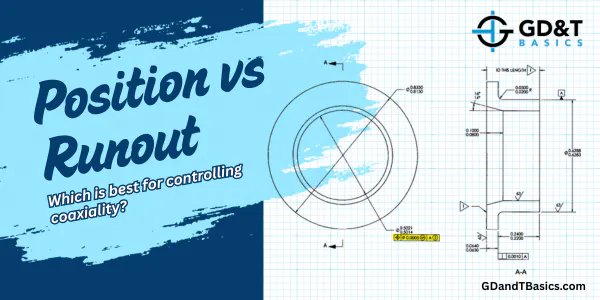
Position vs Runout
Position vs runout explained: Learn how each tolerance controls coaxial features, how they’re measured, and what they actually limit.
Circularity vs runout: Learn the key differences, how each tolerance is evaluated, and what each one controls.
In this Question Line video, Jason walks through how to use different tools and setups to inspect the runout between centers for a submitted part drawing.
Jason walks through the potential issues associated with using V-Blocks and how they can affect measurements of circularity and runout.
In this question line video, we explain when to use the diameter symbol in a feature control frame. The examples below illustrate the unique tolerance zones shapes and sizes for position, perpendicularity, straightness, runout, and cylindricity controls.
The video below is in response to a question that we received on our question line from Jeff. Jeff asked us if concentricity is always equal to half of the runout value. ASME Y14.5 defines...
Controls surface variation relative to a datum axis as the part rotates. Measured at individual cross-sections — simpler and more common than total runout.
Controls the entire surface relative to a datum axis in one sweep. More comprehensive than circular runout — and harder to achieve in production.