Position vs ASME Concentricity
by Crystal Bemis on May 11, 2026.
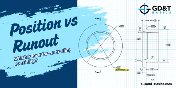
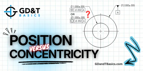
Jason compares position vs ASME concentricity for aligning inner and outer diameters of a cylindrical part, showing how form error impacts the measurements.