
GD&T Symbol: 
Relative to Datum: Yes
MMC or LMC applicable: No
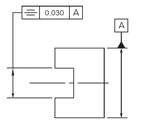
Drawing Callout:
Description:
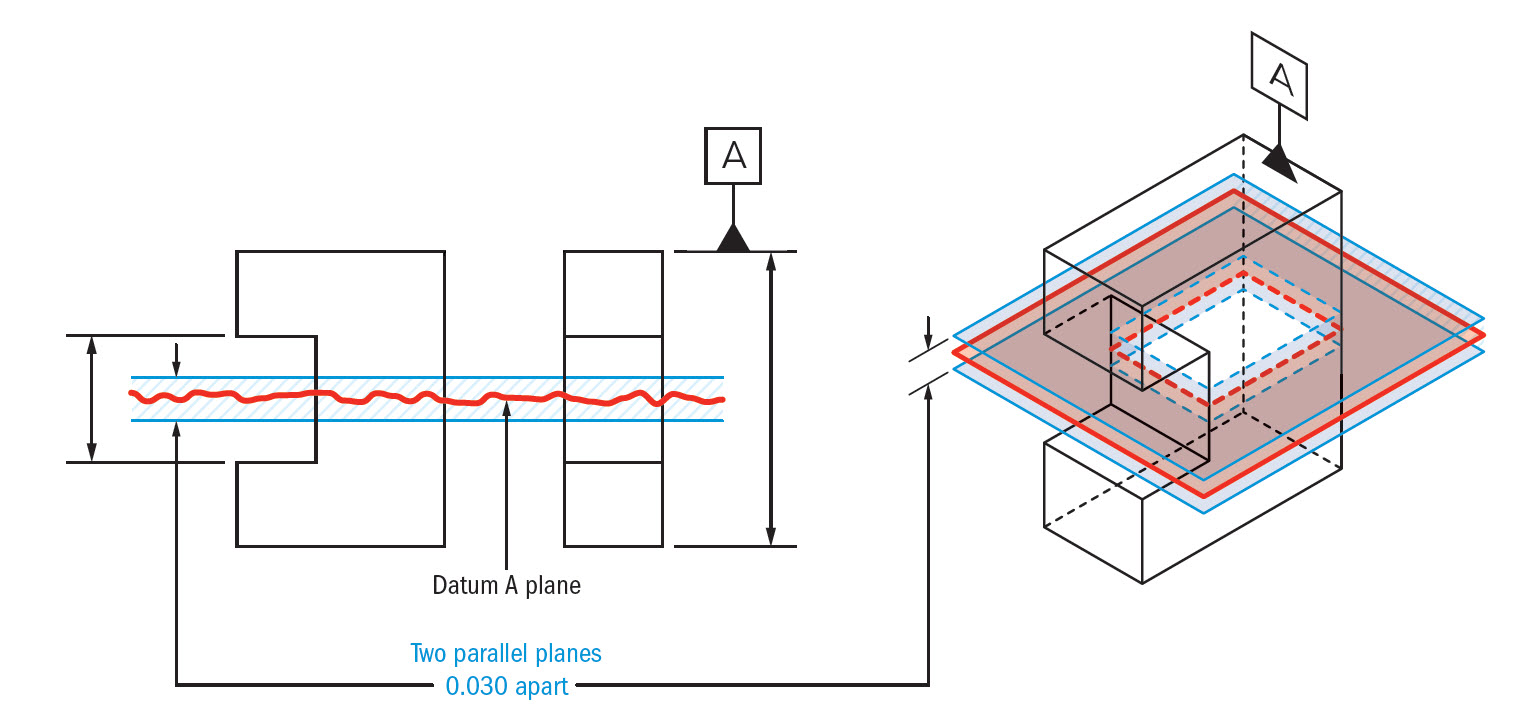
GD&T Symmetry is a 3-Dimensional tolerance that is used to ensure that two features on a part are uniform across a datum plane. An established “true” central plane is established from the datum and for the symmetry to be in tolerance, the median distance between every point on the two surface features needs to fall near that central plane. Each set of points on the reference features would have a midpoint that is right between the two. If you take all the midpoints of the entire surface, this must lie within the tolerance zone to be in specification. Symmetry is not a very common Geometric Dimensioning and Tolerancing callout since it has very limited functional uses (centering location is done with Position) and the verification and measurement of symmetry can be difficult (See: Final Notes).
GD&T Tolerance Zone:
Parallel Planes on equal sides of a central datum plane. The median points of the symmetrical surfaces must all lie within this zone.
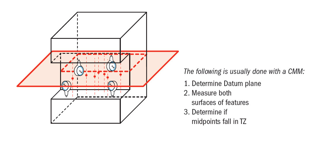
Gauging / Measurement:
As stated before, symmetry is very difficult to measure. Due to its tolerance zone being constrained to a virtual plane, you cannot have a gauge to properly measure this feature quickly. Usually, to measure symmetry, a CMM is set up to calculate the theoretical midpoint datum plane, measure the surfaces of both required surfaces, and then determine where the midpoints lie in reference to the datum plane. This is a complex and sometimes inaccurate method for determining if a part is symmetrical.
Relation to Other GD&T Symbols:
Symmetry is the non-circular version of concentricity. While concentricity really is a focus of symmetry around a datum axis, The Symmetry Symbol is a focus on symmetry over a datum plane. Both symbols focus on the theoretical center datum being constrained within a specific limit to ensure that the entire structure is uniform.
When Used:
When you want to make sure that the center plane of two symmetric features is always held exactly center AND has even form along the surface of the part. This symbol only has specific uses for mass balance and form distribution. However, in most cases it is better to avoid using since this is a very difficult callout to measure and can easily be replaced with a Position tolerance.
Example:
If you had a rotating U-Joint, a groove that needed to always have even balance, you would need to make sure that the mating part is always located to fall into the center of the groove and that the surface form is properly balanced… Instead of widening the groove causing the conncetion to be loose, you could constrain it with symmetry.
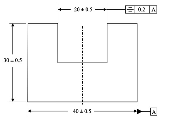
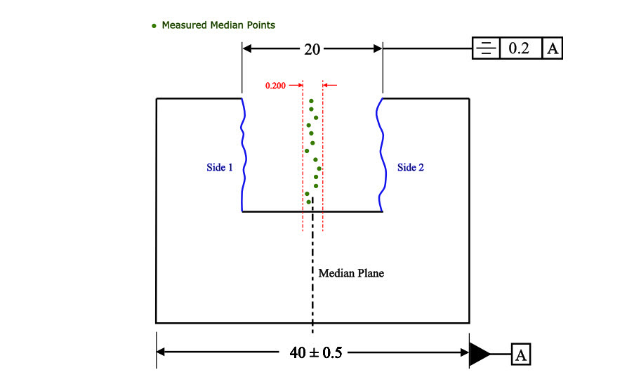
Symmetry Example 1: Call out symmetry to ensure the groove is centered on the median plane of the latch block.
The part would then need to be measured to ensure that all the median points of the sides of the latch block are symmetrical about the central axis. The part would have to be measured in the following way:
- Measure the width and location of both sides of the block reference by datum A (40mm) and determine where the exact median plane is located to establish our tolerance zone.
- Side 1 and Side 2 of the part are scanned for their actual profiles
- Using a program, the median points of the Side 1 and Side 2 scans are laid over the virtual tolerance zone planes and determined if they are in tolerance.
Final Notes:
Symmetry should be avoided in most cases due to its specific functional requirements and measurement difficulty. With flatness, parallelism and true position, you can locate the exact same constraints on the part, albeit with more callouts and measurements required. However since true position can be measured with a gauge (if MMC is used), and flatness is automatically controlled by the size dimension & directly measured off the surfaces, these can be controlled within a process and do not require timely CMM measurements.
Be The Go-To Engineer at Your Company
Learn GD&T at your own pace and apply it with confidence in the real world.
Get GD&T TrainingAll Symbols


A fully threaded rod is having a rectangular cut on one side.. I want to add Symmetricity to It. Can I give threaded area as a datum reference ?
Riyaz –
You can, but you need to specify whether the datum is to be taken as the major diameter, the minor diameter or the pitch diameter. I would also caution against using the symmetry control. It’s difficult to machine to and even harder to inspect for. Additionally, other controls such as position or profile can achieve the same results. Lastly, to hammer the point home, the symmetry and concentricity controls have fallen into such disfavor even with ASME that these two controls are likely to be dropped from the standard in the next revision.
Good luck, I hope this helps.
Matt
I have 4 bosses and two additional touch points on the inside of a housing. There is a profile callout for all 6 of 0.5 to Datum A and Datum B. Then directly below that GD&T, another profile callout of 0.1 to Datum A and Datum B.
I am being told that the first is the profile of all 6 points to Datum A and Datum B. The second is the two touch points in relation to the 4 bosses, to Datum A and Datum B.
Has anyone seen this before?
Chris –
From what it sounds like you are seeing a multiple single segment control. The application is nearly identical to what you would see for position. Using profile, the location of the features of size are being controlled as well as the interrelation of the features of size within the pattern. Without seeing your exact situation it’s a bit difficult to explain in a post, but I encourage you to take a look at section 8.7 and 7.5.2 of the ASME Y14.5 – 2009 standard.
One aspect of your question that I am a bit confused about is whether you are seeing a single profile symbol or two. It makes a difference. It sounds as though you are seeing two profile symbols with one Feature Control Frame directly over the other. If this is indeed the case then the drawing is in error as with multiple single segment controls the datums referenced can’t be a direct repeat of one another. To do so would have no meaning; which control is to be met? If you meet the tighter control all the time you’ll always meet the looser control and then what was the point? Then if you meet the looser control but not the tighter then you’re not meeting your design requirement.
The only scenario where you could have direct repeats of the datums in the feature control frame is with a composite feature control frame where you have a single entry of the profile symbol. Then, the lower control is only restricting the orientation of the tolerance zone defined in the Feature Control Frame. There are some really good examples of this in section 8.6 of the standard.
I realize that this isn’t the complete explanation you were looking for, but I hope it at least provides some insight into what you’re seeing.
Cheers,
Matt
I have a situation where the drawing shows two small surfaces that has a symmetry requirement applied with an axis used for the datum. If you look at the part like it was a clock face, one surface is at 2 o’clock and the other is at 8 o’clock. It doesn’t seem like symmetry is correct in this instance. I would appreciate any thoughts on this. Thank you.
Position would be the best option in 99.9% of the situations that are used. Looks like profile would be best for that situation though to control the surfaces.
Are you sure that the datum center plane should be derived from scanning the sides of the datum feature of size and finding a median plane? I think it should be the center of the actual mating envelope derived from two parallel faces of inspection equipment contacting the datum featute of width from both sides.
In theory – yes it is the center of the Unrelated Actual Mating Envelope from the two surfaces. However the only way to get the UAME would be to scan the surfaces and derive a plane from it. When using a CMM you need to scan the imperfect surface to derive these planes. Great point!
I used look through the ’09 and 94′ revisions of the asme std. I think if you interpret the above example according to shose, datum A should be a centerplane rather a median plane. To derive it you would have to find the center of the actual mating envelope of the 40mm feature of size, gripping it’s surfaces between a vise-like datum feature simulator with “perfectly” parallel two plates. The centerplane of the gap that will be created is datum A. The two faces of the controlled feature – you do have to scan for median points, but not the datum feature. It’s a different way to locate the tolerance zone where you do not have to scan the two external faces. Maybe you interpret it according to a different standard, or there is some exception for establishing a datum for symmetry or something else i am missing?
I see the one image you are referring to and Yes the datum is always a perfect midplane on the part – not derived elements. There is a missing black line on that image showing a perfect plane that the tolerance zone is centered to. Thanks for pointing this out!
Whether the datum plane for symmetry be defined with some other reference such a center of hole? If so how the measurements are applicable there?
Viru –
Can you rephrase your question? I’m not sure I follow.
First, I caution you against overuse of symmetry. It’s a costly and complicated control to produce and inspect that can typically be achieved via another means such as position or profile. Second, all profile controls require the use of a datum (commonly a plane) you are then controlling the mid-points of your feature to that plane. your mid points are defined by a simultaneous two-point measurement of an upper and lower surface for example. The tolerance zone is simply two parallel planes spaced apart an amount equal to your tolerance value.
Symmetry is typically only found in a few specific industry applications as it’s controlling the distribution of mass about the datum. For this reason, unless you have a need to control mass/balance of a part (like say for a tuning fork) your best bet is to use position.
I hope this helps clarify. If you have a specific question let me know and I’ll do my best to answer.
Cheers,
Matt
I measure Symmetry on outside dia and found my center line is 0.19 so my symmetry is 0.38 this is ok. please reply ?
There is a slot (say 10 mm wide) in a block of say (40 mm wide). Symmetry is specified between the centre line of the block and side walls of the slot. In such a case, how to determine the tolerance on symmetry?
I have a question in computing symmetry tolerance. Let say i measured two plane and cylinder as datum reference. If select the cylinder the result is 0.237mm but if i select an axis lets say Y axis , the value is 0.088. which one is correct way to get symmetry
Dear sir,
Good evening….!
i have a product slotted screw. which have a slot on its round head. and as per req. symmetricity of the slot should be 0.20 max. what is the actual method to check this parameter. please advise ….
I have a question
Motor shaft keyway symmetry tolerance is 0.3mm
And pulley keyway tolerance is 0.1 , is this a good design?
and what type of fit will occur if we keep both symmetry 0.3mm?
Ishwar –
I’m not sure I have enough information to make an informed comment on your design. GD&T Basics really can’t comment on the quality of a particular design as we are not intimate and aware of all your design nuances and requirements. I would caution against overuse of the symmetry control, however. Unless you have a clearly defined and specific need for symmetry you can get the same control over the keyway using tolerance of position. Let us know if there is anything else we can do.
Cheers,
Matt
I have a question on reporting symmetry. I have a bearing that slides into a housing and the symmetry callout is 0,4mm. If the centerline of the bearing is shifted 0,1 from the centerline of the housing is my symmetry 0,1 or 0,2?
Thank you
GD&T Tolerances are all total tolerance ranges, meaning 0.1 from the center is a tolerance of 0.2.
Can i apply Symmetry tolerance to a rectangular slab with axis from a cylinder(which is attached to the slab) as a datum?
Symmetry should be applied in 0.1% of situations – roughly 1 in 1000 – only if you are looking for distribution of form only. In this case Position would be much better used.
I want to measure symmetry for the gap(1mm) being created on a annular part O.D 35mm & I.D 30mm. Please help.
Rabi –
I don’t believe symmetry is the best use given the situation you have described. I would suggest looking at a position control and, depending on what exactly you are trying to achieve, either the MMC or LMC control. Symmetry has a select few uses, and unless you are concerned with the distribution of mass I wouldn’t use it. Other potential controls to look out are runnout, but I would only go with symmetry (or concentricity) as a last resort.
I hope this helps.
Cheers,
Matt
As per ASME Y14.5 : 1994, neither symmetry callout nor datum reference can be associated with a modifier. Why??
Aakash –
I’m not sure what you mean by saying that datum references can’t be associated with a modifier. Per the 1994 and the 2009 standard all datums mentioned in the feature control frame are eligible to be used with either the MMC or LMC modifier. Do you mean something else?
As for symmetry, I urge caution when using this control, it’s very a challenging control to machine to and therefore expensive to make and inspect. Now, as to why you can’t use modifiers with it. It has to do with how symmetry controls a feature. By definition: The tolerance zone is 2 parallel planes that are centered about the datum centerplane and the tolerance value control defines the distance between these planes. All of the median points of the toleranced feature (i.e. halfway point of every 2 point measurement) must within this defined zone. Just by examining the tolerance zone you can see that the tangency and the projected modifier don’t make sense. Tangent to what, projecting the zone of what to where? In theory you could use either MMC/LMC but then the end result would essentially be a position control.
I’m struggling with why MMC and LMC can’t be used, to be honest. The best answer that comes to mind is that the ASME Y14.5 committee felt that it would be redundant to using position at best and confusing at worst. I can poke around a bit more and see if I can’t get a better answer for this portion of your question.
Hope this helps,
Cheers,
Matt
Thanks a lot for your reply Matt. The company i work for makes a lot of these parts where there is a trapezoidal feature centered about two parallel surfaces, and everybody uses symmetry to relate the center of the longer base of the trapezoid to the center of the datum feature. We do it by attaching the symmetry control frame to the width dimension on the longer base of the trapezoid. I suspected that it is a wrong practise and your answer confirmed my suspicions:) I’ll keep doing the same thing because that’s what everybody expects and used to ( I’m talking about hundreds of drawings and dozens of years of mass production) but at least I’ll know that it’s not correct…
Hello. I have a simple 2 questions: in all the examples of symmetry call out that i’ve seen, symmetry is always called out on a feature of size that has two parallel surfaces centered about a datum feature. 1. Can symmetry be called out on non parallel surfaces such as on an isosceles trapezoid feature with equal base angles and the sides (legs) are symmetrical about a datum feature on the same part? If it is possible, on which width of the trapezoid the feature control frame should be placed? The small width? The large width? Somewhere between? 3. Can symmetry call out be used to control 2-d line elements on the part instead of entire surfaces? Thank you in advance, s
Simon.
Simon – No, the symmetrical tolerance has to be applied to a singular feature, such as the width or height of a tab/slot. In the scenario you describe the faces of the triangle make up individual features. Imagine a house shape (square with an equal leg triangle on top), both the left and right faces of the triangle are individual faces and have to be controlled separately (except with all around or all over profile). The best way to go about controlling these faces would be with either a surface profile control or an angularity control. I’d also like to encourage you to look more closely at the symmetry control as it really isn’t controlling the form of the surface, but the derived median points of opposed measurements. Sorry for the late reply, I’ve been on vacation and just got back.
Matt
I understand but I can not visualize how is symmetry calculated. Could you detailed describe measuring method?
The measurement is in 3 steps:
First you need to establish your datum plane from the datum feature.
Next you have to literally map out the both surfaces of the referenced feature (where symmetry is called)
Next you have to find the midpoint between all opposing points on the referenced feature. This should give you a series of pints that fall near the middle of the part.
After than you need to determine if all the midpoints fall within the tolerance zone that is the symmetry tolerance apart and perfectly centered on your datum plane from the first step.
All measurement points must fall within this tolerance zone.
Symmetry though is misused about 95% of the time. There are rare cases when it is actually needed. Designers that are unfamiliar with GD&T see symmetry and think that it is nessesary to make a part even. It is not – Position should be used in most cases, as it is way easier to measure and does not take the form of the referenced feature into consideration. You really only need symmetry on symething like a U-joint, where it is rotating at high speeds so the two sides of the pin connection would need to be properly balanced.
And how is this datum plane to be established on the workpiece ? Center of the piece with direction mid-point of both surfaces ?
Robert –
Yes, your datum plane would be a mid-plane determined by two opposing and parallel surfaces. The datum most likely would be determined by using a CMM and created virtually as a reference to compare against when you inspected the symmetry control. I’m not up to speed on the latest metrology techniques, but I’m assuming there is a special tool or method for inspecting the upper and lower surfaces of the feature simultaneously. Alternatively, it’s possible you may be able to simply use the probe to create a contour map (since it would all be digitally created anyway) to compare the upper and lower surfaces against your datum.
Is there anyone else from the community that is able to contribute here?
I hope I’ve been able to help to some degree.
@GD&T BASICS , sir how is symmetry calculated..i mean the formula ..what is it??.cos in my CMM software when i calculate the symmetry of plane with respect to a datum plane (A) it shows me value(2.16) but when i create a mid plane from two plane whose symmetricity is required and then find its dimension (distance) w.r.t to datum plane it shows value(.876) …
I am sorry but I cannot help with a CMM program unless I was standing over your shoulder. All I can tell you is that symmetry controls the distribution of the form of each surface in addition to the position of them. You would need to take the true surface trace in order to calculate it and could not use a simple plane. You are calculating how far out of the tolerance zone (established by the datum) that the surface midpoints lie. YOu need to take a trace of both surfaces fully (which is why designers should avoid symmetry 99% of the time – Use position instead!).
Datum A does not appear to be called out correctly in the GD&T tolerance zone tab. Datum A is called out to be the top plane in that drawing view. It is not called out as width which would simulate the center plane shown in the example. Please correct this to fix misunderstanding.
It should be corrected now, Looks like the second drawing was a little different.
Very Nice & Well represented Information….!!
When one aim is to have (for example) a series of holes in line, true position is most useful. However, when the overriding aim is to have those holes within a tolerance on the centre line of a piece of material, no matter the actual size of the piece of material, then I think the holes position cannot be dimensioned from either side of that piece of material. The centre line of the hole features, needs to be indicated as symmetrical to the centre line of the material, where the material may have a tolerance on its overall width, but only a reference dimension if desired, to its centre line. Position may still be used as it constrains the holes in additional planes not covered by the symmetry. Difficult to label as well as measure. Thoughts please ?
This simple version:
My question is related to symmetry between two angled surfaces… is it legal/reasonable to call out the surface of each leg of a V shaped part as datum A and B, and then have other features be symmetric to a vertical plane that bisects these angled surfaces? I’ll further explain the actual example below…
The complicated version (please excuse the wordiness):
I have a part that is made out of an angle bracket. The stock material angle varies within a few degrees below 90 which is allowable. However, there are features machines into the end of the bracket that become an issue.
Before I get into the GD&T I will explain the part for some clarity (I hope this makes sense). Picture an angle bracket placed on a reference surface so that it forms a tent like triangle pointing up. Offset that reference surface to about half the thickness of the material, and then slice the part. This would result in two chamfer-like flats along the length of the bracket on the inner edges of each leg. Note that since the stock material is not perfectly 90 deg, then this cut in reality should be somewhat greater than 45deg. The final feature is a series of holes drilled in the center of each of these two machined flats.
The design requirements are first that the holes are parallel to each other in the parts free state, and second that the machined flats are visually similar (for aesthetic purposes).
Note the problem I am attempting to resolve is that the parts were originally machined while clamping against a true 90 deg fixture. Thus, when removed from the machine, the flats (machined 45deg from each leg) looked good but the holes were not parallel. Next, the fixture was modified so-as not to stress the part when fixturing but one side was still held flush to the fixture and the angle still cut at 45 deg. This resulted in the holes being parallel, but one flat was visually larger than the other.
We now have a verbal understanding between design intent and manufacturing. The stock angle variance of each machined part will be compensated for but I still need to convey this on a drawing. This leads me back to my original question.
I want to make the outside surface of both legs datum A and B. Then I think I want to call out the width of both flats in a single callout as: 3/8″ [symm][.062][A-B] 2 places while the 45 deg angle I suppose is reference (the .062 tolerance is intended to be large enough to determine by eye). This just feels rather convoluted to me but I am struggling to come up with a better alternative.
The holes are a bit simpler. I feel fairly decent calling out [position][Ø.014″(F)][A][B] typ. Note the position of the pattern along the length of the part is not critical – thus I omitted the third datum in the FCF.
Dear all Symmetric has been applied to outer dimension??. Examle take on squre block 20x20x20 whether Symmetric was applicable for that 20x20x20. pl Help me
Symmetry is only applied to a feature of size (feature with a dimension) and requires having a datum plane to establish the symmetry. Symmetry in GD&T does not just mean symmetric (english definition) it is a very detailed control that ensures all median points of one feature, are with a tolerance zone established by a datum feature plane. IT SHOULD BE AVOIDED 99.9% OF THE TIME SINCE IT IS VERY SPECIFIC. You are controlling the location of your feature and the distribution (not magnatude) of the form on the part. The True Position symbol can make something symmetric fairly easily without being a huge pain to measure.
Hello there…I take exception to your graphic above with the cylindrical zone symbol being in the feature control frame for the symmetrical tolerance on a feature of size that is not cylindrical. You are tolerancing a slot not a hole thus your tolerance zone is two parallel planes as stated, not a cylindrical zone.
I was researching the symmetry tolerance as I have a client that asked my advice on an optical part wit the callout specified. I am not at liberty to divulge the client or their customer. Since I don’t have my standard on hand ( I have left it with another customer somehow and never got it back) I had to look it up. I have taught the basics in the past, but have been away from GD and T for a time. It’s one of those, Use it or lose it things. I love 0 at MMC…it works.
Best,
Paul
Sorry about the confusion, we took the same Feature Control Frame from concentricity… but then forgot to take away the Ø Symbol! Thank you for letting us know so we could fix it. Symmetry should really be avoided in 99% of the situations where it is used. I would say in most cases true position with perhaps a flatness requirement should be enough to control it. Symmetry should only be used when you want to control the distribution of the part form, but do not care how much magnitude of the form error exists. Thanks for the heads up!
I have a case here where symmetry of 0.03mm is give to a through drill hole 180 apart on a housing having ID = 200mm and OD = 250 mm. These 2 holes need to be symmetric to the plane perpendilar to the axis of the 2 holes. Now the 2 holes have to be concentric as well within Ø0.05mm. My question is how do I measure and inspect symmetry?
The concentricity callout seems okay, but is always a pain to measure since you need to setup your datum axis and your feature axis and then use software to find the central points. Thy symmetry callout is a bit strange, seeing as simply calling concentricity of 0.03 would automatically take care of both tolerances. Most of the time I have ever used symmetry it was for two flat surfaces. If this is an ISO drawing there could be a slightly different interpretation of this. The ASME y14.5 standard states: “Symmetry is that condition where the median points of all opposed or correspondingly located elements of two or more feature surfaces are congruent with a DATUM AXIS or center plane.” So you can use a central axis to measure symmetry, however you would absolutely need another datum to orient your tolerance zone. You would need to create a datum plane from your two datums, then calculate all the median points to this datum plane at every symmetrically opposed point on the feature, and finally use software to determine if all of those median points fall within a 0.03 flat tolerance zone.
One thing that a lot of design engineers do not understand about symmetry is how overly restrictive it is and how its is only necessary about 5% of the time. A basic position tolerance is probably all that is needed for the application unless it is load balanced and rotating. Symmetry on a round part seems like the designer was being a little overambitious and would have been better off (and probably less expensive) to use a true position tolerance on the part to get the same functional result. Most people hear symmetrical and think it just means “even” – its much more than that.
Being a designer myself, I can say I cannot truly think of a case where symmetry should be used for the ASME Y-14.5. It has such a rare case where the distribution of material need to be uniform over a plane. When you need it, profile or position pretty much always can do the same functional thing.
I NEED TO CHECK A SYMMETRY ON A PLANE.
A HOLE HAS BEEN DONE ON AN OUTER DIAMETER OF (Ø 3MM+/-0.1) BUT HE HAS ASKED THE SYMMETRY FROM THAT HOLE TO THE OUTER Ø.
KINDLY HELP TO MEASURE IT.
I’m sorry, due to legal reasons we do not consult on the site for specific design issues you may have, only answer questions on theory and interpretation of the standards. All I can tell you is that symmetry is usually only applied to planar objects and true position seems like a better tolerance for hole locations.
Let me know . The meaning of GD &T (ALL SYMBOLT Of GD &T.) thank a lot.