

V-Blocks are popular tools used during many types of manual inspections. However, they come with a unique pitfall that can impact the accuracy of measurements. In the video below, Jason walks through the potential issues associated with using V-Blocks and how they can affect measurements of circularity and runout.
In the example below, we have a cylinder with two bosses, one on either side. The OD of the cylinder is shown to be 1.500 with a +/-.015 tolerance. By default, GD&T Rule #1 would control the circularity error of this cylinder based on that size dimension. However, this feature also has a circularity control attached which refines the allowable circularity error to a smaller tolerance of .01.
This means that the difference in the radial measurements from the center axis to the highest point on the OD and to the lowest point on the OD must be less than .01 to meet the circularity specification.
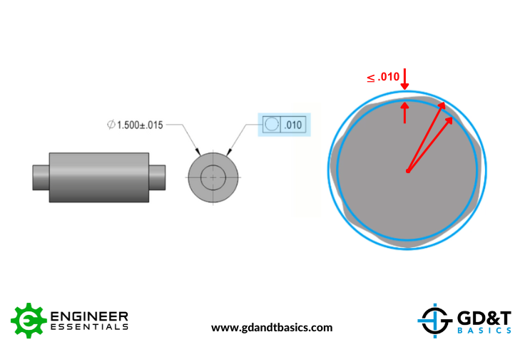
Figure 1: Circularity Error of a Cylinder
So how is circularity inspected? Many times, a V-Block is used to allow rotational freedom of the feature while radial deviations are recorded on an indicator. The cylinder is placed within the V-Block and rotated, ideally about the axis of the feature, and the Full Indicator Movement (FIM) or Total Indicator Reading (TIR) is recorded during one full rotation of the cylinder.
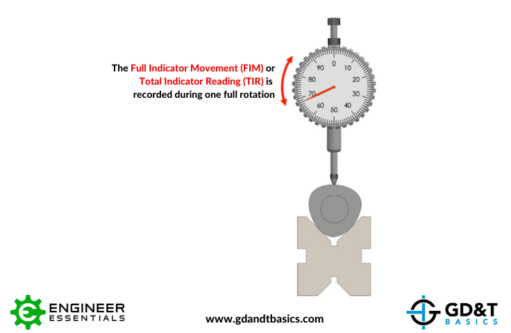
Figure 2: Circularity Measurement of a Cylinder using V-Blocks
The pitfall to this technique is that the interaction between the geometry of the V-Block and the geometry of the surface being rotated does not necessarily give us an axis of rotation. Consider the tri-lobed cylinder shown in the figure below. If we placed the tri-lobed cylinder in a V-Block, the high points of the of the cylinder would settle into the V-Block, making the entire part drop down and moving that axis of rotation.
Figure 3: Tri-lobed Cylinder Circularity Measurement using V-Blocks
The axis of rotation must be fixed with respect to the indicator to get accurate readings. If we compare the measured error value using V-Blocks with the actual error value, we can see that the measured value is about 2x larger than the actual amount of error.
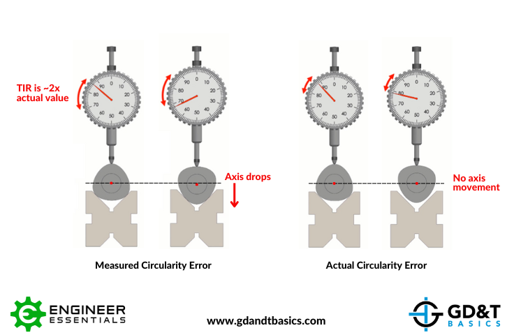
Figure 4: Tri-lobed Cylinder Axis Drops When Using V-Blocks
You may assume from the above example that the error value measured using V-Blocks is always conservative, and if your measured value is within the tolerance, your part is within spec. However, the quad-lobed cylinder in the example below proves that this is not always the case. With four high points, we can see that the movement of the axis results in measurements that are much smaller than the actual amount of error.
Figure 5: Quad-lobed Cylinder Circularity Measurement Using V-Blocks
In this scenario, you may have a part that is indicated as good, but the actual error is more than twice as much as what is indicated.
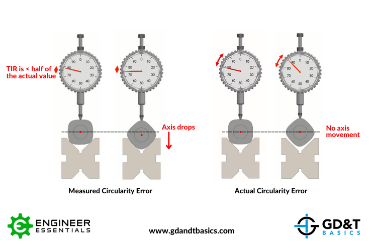
Figure 6: Quad-lobed Cylinder Axis Drops When Using V-Blocks
Conclusion
V-Blocks are handy tools that aid in manual inspections, but you must understand their limitations to avoid errors in measurements. If you are using them to measure runout, circularity, or anything that creates an axis of rotation, you need to be aware of the pitfalls we have discussed. V-Blocks can be used as quick sanity checks, but if tolerances are tight, other equipment, such as a runout checker or polar probe, should be used for precise measurements. Remember, knowledge of the tools we use is always essential when striving for precision in metrology.
The one-page GD&T reference that you will use every day
A visual breakdown of every core GD&T symbol and what it controls, all on one page. Bookmark it. Print it. Actually use it.
Download the Chart