

“How do I inspect position if my drawing references ISO?” In today’s Question Line Video, Jason looks at a part with a cylindrical hole feature and compares the ASME and ISO standards for controlling the position of that hole.
In the drawing below, we have a part with a cylindrical hole through its center, where the cylindrical hole is being controlled with a position tolerance of .005. The Feature Control Frame would look the same for both ASME and ISO GD&T standards, and both standards are controlling the position of the central elements of this hole to be within a cylindrical tolerance zone. The difference between the two is in how the central elements of the hole are obtained.
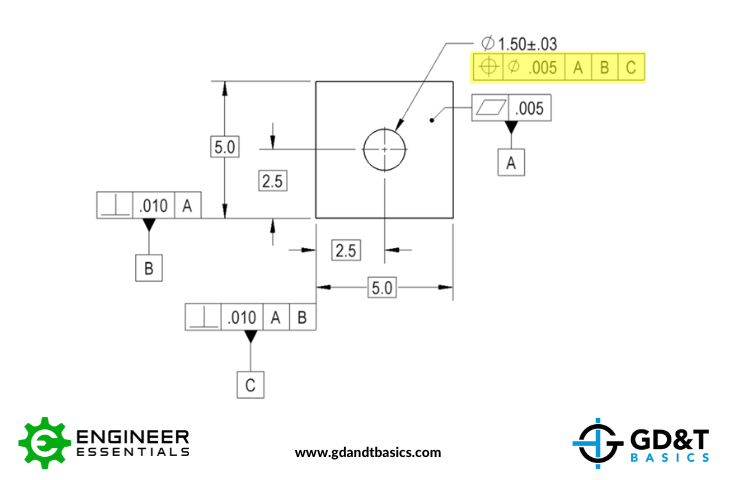
Figure 1: Cylindrical hole controlled with GD&T Position
ASME Position Method
To determine the central points of this imperfect cylindrical feature, the ASME standard instructs us to use the Unrelated Actual Mating Envelope (UAME). The UAME is a theoretical cylindrical envelope that expands inside the feature until it settles on the high points of the feature. We then derive an axis from this perfect cylindrical envelope. If the axis lies fully within the position tolerance zone, the feature passes the position specification. This is represented below in Figure 2, with the position tolerance zone in indicated in blue, the UAME in light gray, and the axis derived from the UAME shown in red.
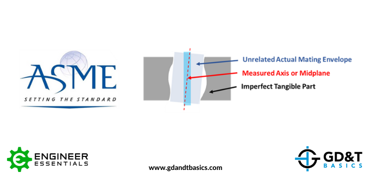
Figure 2: Determining the Central Points of the Cylinder with ASME
ISO Position Method
The ISO standard determines the central points of the cylindrical feature in a different way. Instead of using the Unrelated Actual Mating Envelope to determine the axis of the cylinder, ISO uses the Extracted Integral Feature to determine the Extracted Derived Feature. This looks like taking cross sections of the cylinder and finding the center points of each section. The center points create an abstract line, which is the Extracted Derived Feature. This Extracted Derived Feature must stay within the cylindrical position tolerance zone to pass the position specification. This is represented below in Figure 3.
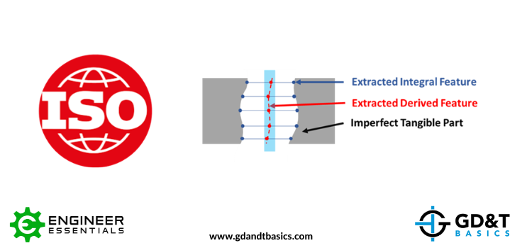
Figure 3: Determining the Central Points of the Cylinder with ISO
Inspecting Position
ASME and ISO standards do not specify how to physically measure the parts for inspection. Depending on what you are using to measure position, you may be doing a hybrid of both ASME & ISO methods. Using a best fit gage pin is most similar to mimicking the Unrelated Actual Mating Envelope of the ASME method, while measuring a cross section and finding the midpoint is closer to the ISO method. As an inspector, it is your job to follow the standard as closely as possible without spending excessive amounts of time and money to confidently say that the feature passes inspection per the standard that you are using.
The one-page GD&T reference that you will use every day
A visual breakdown of every core GD&T symbol and what it controls, all on one page. Bookmark it. Print it. Actually use it.
Download the Chart