
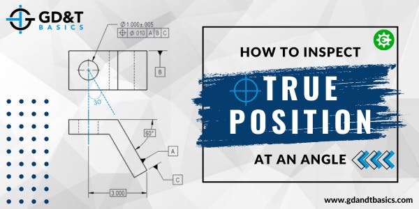
Typically, when a hole is being controlled with position, the primary datum is often the surface that the hole originates from and the secondary and tertiary datums are perpendicular or parallel to the primary datum. However, this is not always the case. In this video, Jason walks through an example drawing to show us how to inspect a hole that is at an angle with respect to the primary datum.
Inspecting Position at an Angle
In the drawing below, we have a part where the primary, secondary, and tertiary datums establish a datum reference frame that creates a unique scenario for inspection. Specifically, we are looking at the relationship between the axis of the hole that we are controlling with position and the primary datum. From the basic dimensions listed on the drawing, we can calculate the orientation of the axis of the hole to be 30 degrees from the Datum A. How do we inspect the location of this angled feature with respect to the datum reference frame?

Figure 1: Hole Feature at an Angle from the Primary Datum
To inspect the location of this hole, we must fully simulate the datum reference frame. Datum B, the back surface of the part, could be easily simulated using a gauge block, which is very easy to set up and inspect. So, for this example, we will ignore the effects of Datum B and focus on Datums A and C.
As illustrated in Figure 2, a Sine Plate could be used to simulate Datum A, and a stop at the end of the plate could be used to simulate Datum C. By doing this we are simulating the perpendicularity of Datums A and C, giving us the zero point (0,0,0) from which we can reference the location of the hole.

Figure 2: Datum Reference Frame Simulation
However, there is an inherent flaw when physically trying to inspect this part. When using a height gage, you are not able zero the gage at the intersection of the two planes because the probe will not settle at the zero point. Therefore, you must use a pin and trigonometry in order to offset your measurement. Figure 3 shows an enlarged view of a pin placed at the intersection of the two plates. This pin is of known diameter, and the distance from the top of the pin to the zero point will be calculated (X) to determine the amount of vertical offset for the probe measurement.

Figure 3: Pin is Placed at the Intersection of Datums A & C Simulators
Trigonometry is used to calculate the value for X, the vertical offset, using the known values for the pin radius and the 30-degree angle. Jason walks through these calculations in detail in the video. The resulting equations are shown in Figure 4.
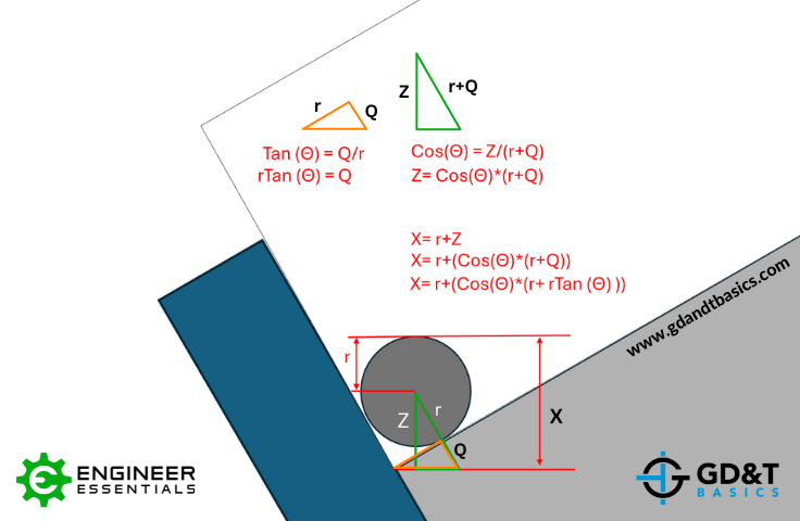
Figure 4: Calculating the Vertical Offset
Once the vertical offset is known, we zero our height gauge off of the top of the pin, and then we move down the X amount that we calculated to re-zero the gauge. We are now taking our height gauge measurements from the intersection of the two plates. This allows us to determine the deviation of the hole in the Y direction.
We would then need to create another simple setup to simulate Datums A and B to get the deviation of the hole with respect Datum B. With these two deviations known, we can then calculate the diametric deviation of the hole. This is illustrated in Figure 5. As long as the diametric deviation is less than the tolerance allowed, the point that you calculated passes inspection.

Figure 5: Determining the Diametric Deviation
However, that is just one point checked in the depth of the cylinder. The appropriate points must be taken to ensure that the entire axis is being checked. In reality, a best fit gauge pin should be used to simulate the unrelated actual mating envelope (UAME) of the cylinder and then we can measure off that cylinder to create a theoretical axis. See the video for full details.
Summary
Inspecting position at an angle is less straightforward, but can still be done using some trigonometry. Jason walks us through an example where our zero point was inaccessible to our height probe due to the angle of the datums. This was overcome by using a pin of known diameter to help determine the amount of vertical offset to zero the probe, allowing for accurate measurements.
The one-page GD&T reference that you will use every day
A visual breakdown of every core GD&T symbol and what it controls, all on one page. Bookmark it. Print it. Actually use it.
Download the Chart