

In this Question Line Video, Brandon explains Rule #1 of GD&T (the Envelope Principle) and how a go gage and no-go gage are used to verify that Rule #1 is met for a feature of size.
Rule #1 – Envelope Principle
Rule #1 of GD&T, also known as the Envelope Principle, states that the surface of a feature of size must conform to a boundary (envelope) of perfect form at the Maximum Material Condition (MMC) size. In other words, the size tolerances of a feature of size also control the form of the feature. This is one of the core principles of the ASME Y14.5 GD&T Standard.
Let’s look at an example to visualize the envelope principle. In the example below, we have a block with a cylindrical hole through it. The hole is dimensioned with a diameter of 1.50 with +/-.03 tolerances. These tolerances result in the MMC size of the hole equal to 1.47 and the LMC (Least Material Condition) size equal to 1.53. The red cylinder in Figure 1 represents the MMC envelope, which no element of the surface of the bore can come inside.
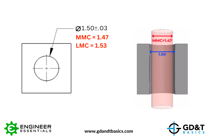
Figure 1: MMC Envelope of a Cylindrical Hole Feature
The allowable amount of form deviation is determined by the difference between the measured size and the MMC size of the feature. When the measured size of the feature is at MMC, it must have perfect form. Perfect form is impossible to achieve, so a feature measuring at MMC would be rejected. As the size of the feature departs from MMC, more form deviation is allowed. With this being a cylindrical feature, the result is more allowed deviation in circularity and straightness. The maximum amount of form deviation allowed occurs when the feature is measured at its LMC size.
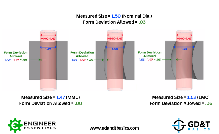
Figure 2: Form Deviation allowed at MMC, Nominal, and LMC Measurements
Go & No-Go Gaging
When we are relying only on Rule #1 to control form, the form error does not get reported. However, it must be checked as a pass/fail for the Rule #1 requirement. This is most commonly checked through Go/No-Go gaging.
A “Go” gage is a fixed limit gage that checks a feature of size for acceptance within the MMC perfect form boundary (the boundary illustrated by the red envelope in the previous section).
A “No-Go” gage is a fixed limit gage that checks a feature of size for violation of the LMC actual local size.
For the feature to pass inspection, the Go gage must fit, and the No-Go gage must NOT fit.
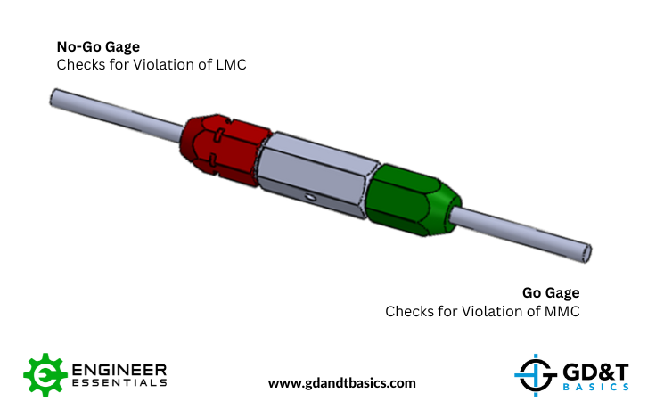
Figure 3: Pin Go/No-Go Gage
According to ASME Y14.43, the Dimensioning and Tolerancing standard for Gages and Fixtures, the tolerance of the gage itself must be within the size limits of the workpiece. This is defined as the “Absolute Tolerance Policy”. This means that the tolerances given to the gage will effectively reduce the workpiece tolerance available. This can result in good parts failing inspection, but will ensure that bad parts will always fail.
Pin and Ring Gage Tolerances
For Pin and Ring Gages, the standard practice is to allow 5% of the hole tolerance for the Go Gage and 5% for the No-Go Gage tolerance. Once you have calculated your Gage tolerance, you can determine the tolerance class of the required gage by referring to a Gage chart, such as our Gage Maker’s Tolerance Chart shown below. Tolerances in the chart come from ASME B89.1.5 (Pins) and ASME B89.1.6 (Rings). Details on calculating gage tolerance and determining tolerance class are explained in the video above.
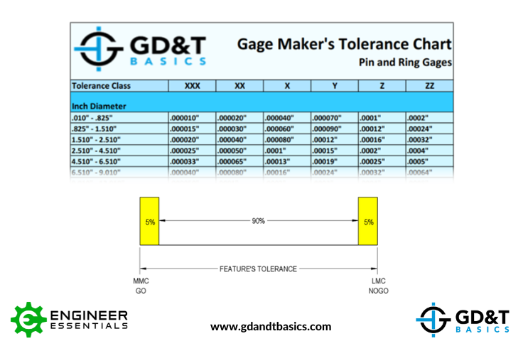
Figure 4: Tolerances for Pin and Ring Gages
Gage Block Tolerances
Precision Gage Blocks are used for Go/No-Go gaging and many other applications. They are made of steel or ceramic, and can be stacked together (wrung). When properly wrung, the gap between the blocks is around one millionth of an inch. Check out this video from Mitutoyo for more information regarding Precision Gage Blocks: www.mitutoyo.com/educational-resource/mitutoyo-gage-blocks/
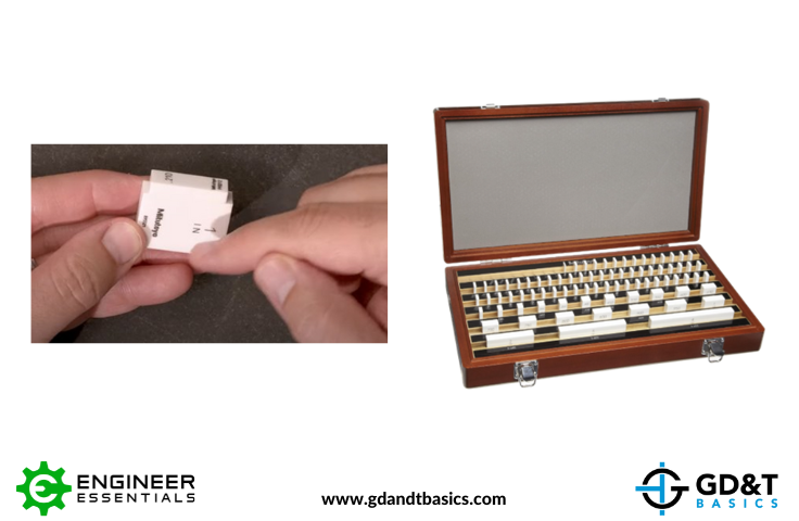
Figure 5: Gage Blocks
Inspecting with a CMM rather than a Go Gage
If you are inspecting parts using a CMM rather than Go/No-Go gages, you still need to ensure that Rule #1 requirements are being met if your drawing references ASME Y14.5. Always verify that your CMM is doing the appropriate Rule #1 inspection.
For information on CMM – GD&T Measurement Planning, check out this resource from Mitutoyo:
www.mitutoyo.com/educational-resource/cmm-gdt-measurement-planning/
The one-page GD&T reference that you will use every day
A visual breakdown of every core GD&T symbol and what it controls, all on one page. Bookmark it. Print it. Actually use it.
Download the Chart