
Even the most impeccable CAD drawings won’t be produced perfectly every time. That’s why engineers need Geometric Dimensioning and Tolerancing (GD&T) to define precisely how far from “perfect” a part can be and still function.
Unfortunately, most engineers don’t receive courses like “GD&T for dummies” as part of their technical training. So, they mistakenly assume that the old way of coordinate dimensioning is good enough, and that the concepts behind GD&T seem too complicated or the jargon sounds too confusing to learn.
However, when you approach GD&T as a way of simplifying the manufacturing process instead of complicating it, you’ll realize that GD&T training doesn’t have to be complex or boring – it can actually make your life easier and your products better. Here’s how we simplify the formidable world of GD&T by making it easy to understand and practical to use.
Why Engineers Need GD&T Basics
Why Traditional GD&T Training Falls Short

Why Your Manufacturing and Engineering Teams Need GD&T Basics
Back when the entire manufacturing process stayed in-house, companies could control every step – from design through production to inspection. In the old days, typical coordinate dimension prints were good enough to communicate general dimensions, because companies knew instantly whether a finished part matched their print or not – and if it didn’t, they could pause the press and quickly make adjustments to fix it.
But as more companies began outsourcing more aspects of the manufacturing process, they lost control of how designs were being produced. Vague coordinate dimensions and simple +/- tolerances left parts open to dozens of interpretations. Sure, the hole might be the right size and located in the right place as indicated on the drawing, but it might be slightly oblong instead of perfectly round. If the designer didn’t specify roundness, this could pass inspection – and then pass thousands of imperfect parts onto assembly, where the bolt might not fit properly into the hole, rendering all parts as scrap.
Without GD&T, a design might invite so many different readings of a dimension or tolerance that the final product could be completely nonfunctional – even though it technically meets the requirements on the print. GD&T keeps everyone on the same page throughout the entire manufacturing process by clearly defining the only acceptable interpretation of each tolerance and dimension.
What is GD&T?
To illustrate what GD&T is and what a big difference it can make on any manufactured product, we often use mirrors as an example to start our GD&T training courses.
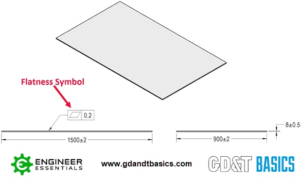
In the past, product designs for mirrors might only indicate the size and thickness required for the mirror to fit into its frame. True to print, a mirror might fit those dimensions when measured by an inspector. But if there’s nothing on the drawing to specify how flat the mirror must be to provide a realistic reflection, then that perfectly sized product might be as wavy as a funhouse mirror. Unless you’re designing a new carnival attraction, that’s probably not what you want.
To control these variations, product designers use GD&T to specify a mirror’s intended flatness in addition to size and thickness. They might also use GD&T to describe manufacturing priorities – meaning, if the flatness of a mirror is more important than its thickness, the drawing would indicate a looser tolerance on the thickness and a tighter tolerance on the flatness to ensure that the end product will work as intended.
So, what is GD&T, exactly? GD&T is a universal engineering language that uses standardized symbols to define the size, location, orientation, and form of any feature on a given part. In our GD&T Basics framework, we refer to this as S.L.O.F. These are the only four ways you can control and define the geometry of anything, from a simple pair of scissors to a complicated ball bearing assembly. Once you grasp this basic idea, you have a solid foundation for learning how to apply GD&T to any manufactured part.

Why Traditional GD&T Training Falls Short
The current U.S. standard for Geometric Dimensioning and Tolerancing spans a daunting 350-page document, called ASME Y14.5-2018, that might intimidate even the most experienced engineers. But here’s what most GD&T teachers don’t tell you: The entire 350-page standard is basically giving you different ways of defining those four simple S.L.O.F. concepts. That doesn’t seem so intimidating, now, does it?
The problem is that most GD&T training courses teach this standard tediously by making students memorize the full set of rules, instead of explaining how these rules impact modern manufacturing. Rather than starting with simple examples of everyday objects like mirrors, most courses jump right into the 14 symbols used in GD&T – even though most engineers will only see a fraction of those throughout their entire careers. Hopefully, these courses eventually circle back around to explain how to apply these foreign symbols on real drawings before the whole class falls asleep.
Many GD&T instructors tout themselves as GD&T evangelists who offer comprehensive training and enforce strict adherence to the rules. But by focusing on the rules more than the real-life applications, students often leave the class confused – prepared to throw a bunch of complex symbols on a drawing, but not really equipped to effectively apply the concepts of GD&T to simplify production at their plant.
No wonder so many people are reluctant to sit (or snooze) through this kind of training!
GD&T Basics’ Approach to Training
At GD&T Basics, we teach the system, not the standard, so you can use GD&T to make better engineering decisions instead of getting headaches trying to memorize a 350-page rulebook. Our goal is not to make you an expert; we just want to make you more efficient.
To that end, we don’t kick off our courses by focusing on what the standard says. We focus on the core concepts you need to know about GD&T to improve your drawings, your production process, and your inspection guidelines – using the standard as more of a reference than a roadmap to our curriculum.
As engineers with over 30 years’ combined experience in the field, we’re realists when it comes to teaching GD&T. We focus on real-world applications, not theoretical concepts. Based on our experience, we developed the GD&T Basics Framework – GD&T for dummies, if you will – to simplify the complex ideas behind GD&T. That doesn’t mean we dumb down the material; we just make it directly applicable to your production process, instead of dumping a huge book full of jargon on your desk.

GD&T Made Easy
If you browse through GD&T books on Amazon, most of the negative reviews mention the lack of real-life examples. Likewise, one of the biggest complaints about typical GD&T training is that most courses rely on unrealistically simple examples by applying GD&T to a box, a sphere, or another basic shape. Most engineers are designing parts much more complex than that, so after you finish one of these classes, it’s tricky to translate GD&T from a simple cylinder onto a real part in your shop.
To gain confidence and competence using GD&T every day, you need experience with real-world examples from actual drawings. That’s why our GD&T Basics training courses, both online and live training, center around real manufacturing prints rather than oversimplified examples. Rather than relying on GD&T theory, we focus on practical applications that you’ll actually use on the job.
To make our training as applicable as possible, we customize our courses for each client by modifying examples and explanations to the parts you’re actually making. We curate the concepts that you’ll actually use and skim over the confusing theories that won’t impact your work, using your real drawings to make GD&T more approachable.
Most importantly, we go beyond the print to explain how GD&T really impacts your daily workflow and your production results. As your guides and translators on the GD&T journey, we walk you through every aspect of:
- How to apply GD&T to prints
- How to interpret GD&T symbols on drawings
- How to develop inspection plans from GD&T specifications
Whether you’re putting GD&T on a drawing, producing parts from that drawing, or inspecting the final parts, you’ll leave with a practical working knowledge of how GD&T can help you make better decisions at every point of the manufacturing process.
Once you learn how GD&T can simplify your job instead of overcomplicating it, you’ll understand how to use it to:
- Communicate complex design requirements more clearly
- Settle disputes between machinists and engineers
- Increase part manufacturability
- Minimize scrap parts
- Reduce production costs
- Improve product quality
Our GD&T training won’t make you an instant expert in a language that takes years to master. But our GD&T Basics courses will give you the tools to be a better designer, a better machinist, or a better inspector by mastering practical applications of GD&T made easy.
We want to help you figure out the best approach for getting your team using GD&T. We are here first to help - not sell, so let us know how we can assist your team to get started with GD&T Training.
