

In today’s Question Line Video, Jason uses the example of a cylindrical datum feature to show how non-planar datums can be simulated and how they are able to constrain degrees of freedom.
We received the following question from a student: “I understand how planar datums constrain degrees of freedom. But I still don’t understand how an axis or point datum is supposed to constrain degrees of freedom. With planar datums, you can picture it as a datum simulator, but how do you do that with an axis or point?”
To begin, let’s review some terms. A datum feature is the tangible, imperfect surface or feature of size on a part that is indicated by the datum feature symbol on the part drawing. Datums, which are theoretically exact points, axes, lines, or planes, are derived from datum features. They are used to create a datum reference frame – the reference system used for inspecting the manufactured part.
So, how do we measure from a theoretical datum? We must simulate the datum using measurement equipment. For a flat surface indicated as a datum feature, the derived datum would be a plane. To simulate this datum plane, we could use a granite table (or surface plates). We would then engage the datum feature with the datum simulator, placing the surface on the granite table. Once we have engaged to a datum, we cannot disengage it. Therefore, we see that we have restricted the movement of the part by one translation (up and down) and two rotations (left & right rotation and the rotation into & out of the page), for a total control of three degrees of freedom.
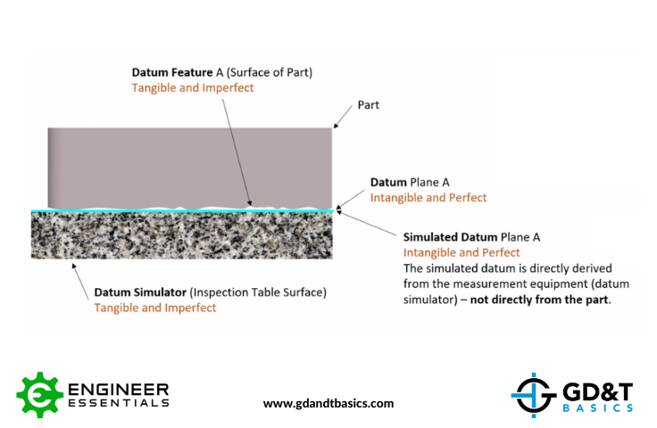
Figure 1: Datum Plane Simulated using a Granite Table
Now back to the student’s question. How can we simulate non-planar datums, and how are they able to constrain degrees of freedom? To answer this question, let’s consider a part with a cylindrical datum feature.
The resulting datum from a cylindrical feature would be an axis. To simulate this datum axis, we would first need to simulate a perfect cylinder that encompasses the actual cylindrical datum feature surface, one that touches the high points of the feature surface. The axis of this perfect cylinder is the datum axis.
To simulate this with measurement equipment, we could use a 3-jawed chuck, as shown in Figure 2, below. This chuck engages the highpoints of the cylinder, and when we rotate this part, we will get an axis of rotation. We can then take measurements back to this axis.
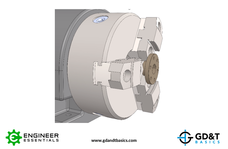
Figure 2: Datum Axis Simulated Using a 3-Jawed Chuck
Another method we could use to simulate a datum axis is using V-blocks. If we have two datum features that create a single axis of rotation, we can set those features on V-blocks and rotate the part. Rotating the part creates an axis of rotation that we can use as a datum simulator, and measurements can be made back to that simulated datum.
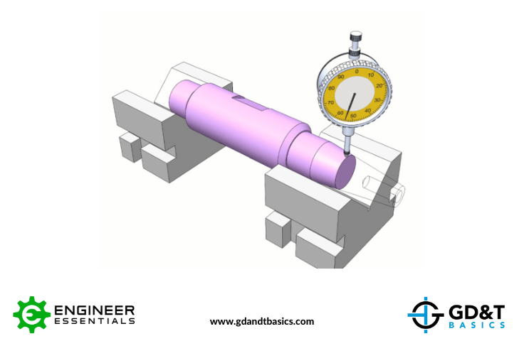
Figure 3: Datum Axis Simulated Using V-Bocks
In engaging our datum simulators, we have stopped two degrees of translation and two degrees of rotation. The two degrees of freedom that have not been constrained are the translation in the direction of the axis and the rotation about the axis.
Summary
Both planar and non-planar datums can be simulated by measurement equipment. With our part engaged to datum simulators, we are also simulating the constraints on the degrees of freedom of the part. When inspecting the part, we take our measurements back to the simulated datum. The more accurate our datum simulators are to representing the datum, the more accurate our measurements will be.
The one-page GD&T reference that you will use every day
A visual breakdown of every core GD&T symbol and what it controls, all on one page. Bookmark it. Print it. Actually use it.
Download the Chart