
Do you know how dimensions and tolerances for complex parts are measured? Often, a coordinate measurement machine or CMM is used. In this article, we will look at different types of CMMs and discuss how they work and when they are used.
What is a Coordinate Measuring Machine?
A coordinate measuring machine is an instrument that is used to collect measurements of three-dimensional objects. A CMM consists of a structure that moves in three dimensions, a probe attached to the structure, and a computer control and/or recording system. All coordinate measuring machines operate in the same way: the probe touches points on the object to be measured, and the position of the structure is recorded. Each measurement point is described by X, Y, and Z coordinates. All the measured points for a single object are combined into a 3D CAD file known as a point cloud. The point cloud can be compared to a 3D design drawing to determine if the object has been manufactured to the correct dimensions.
Types of CMMs
CMM’s come in all shapes and sizes, depending on the objects to be measured. The smallest CMM’s can be portable, but the largest CMM’s require a custom concrete foundation. Articulating arm, horizontal arm, bridge, and gantry are some of the common CMM configurations. Below, we will discuss general characteristics of each configuration.
Articulating Arm
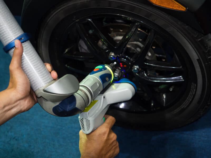
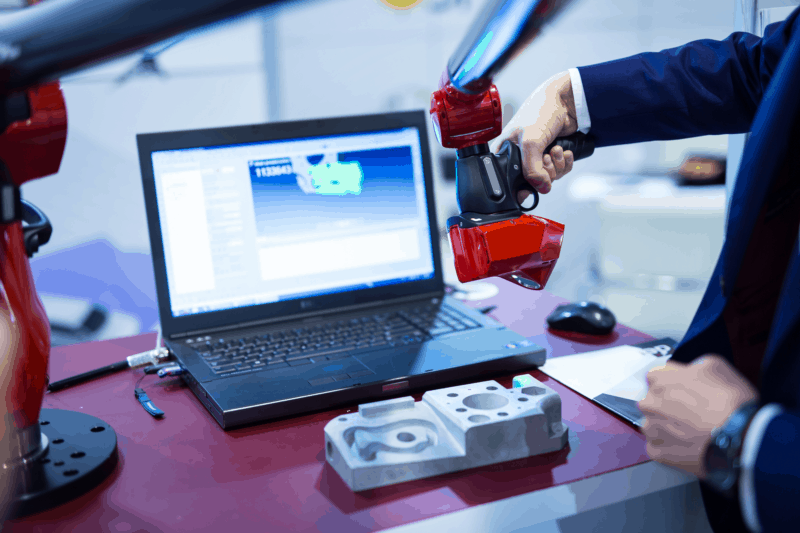
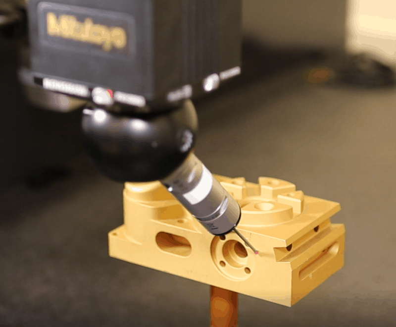
These compact, versatile CMM’s consist of a vertical post with multiple articulating segments and up to 8 axes of movement. A probe is mounted to an articulating joint at the end of the arm, and they often have a laser scanning apparatus allowing for the use of either or both at the same time. The articulating joints allow the probe or scanner to be angled to collect measurements in hard to reach areas. These machines are manipulated by hand to place the probe or scanner at the point to be measured. The photos below show articulating arm type CMMs in use.
These CMM’s are highly portable and do not require climate-controlled rooms for operation. They can be used to collect field measurements from installed parts. Advertised accuracy is as high as 0.0002”, but the setup’s environmental conditions can limit it. Additionally, the measuring range of these machines is limited only by the arm’s reach, so they can be used to measure a wide variety of parts, making them well-suited for many commercial machine shop applications. However, articulating arm CMM’s cannot perform an automatic measurement, and they are not typically used for measurement in high-volume manufacturing processes.
Horizontal Arm
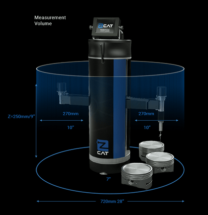
The basic structure of this type of CMM consists of a base with one or more articulating arms or beams. A probe is mounted on a rotating joint at the end of the arm. The arms can be extended or retracted from the base in any direction and will also pivot about the base, allowing for measurements in three axes. However, for some configurations, the probe is capable of traversing perpendicular to the base on a horizontal arm, providing a third measurement axis. The photo below shows a portable, rotating, horizontal arm type CMM manufactured by zCAT.
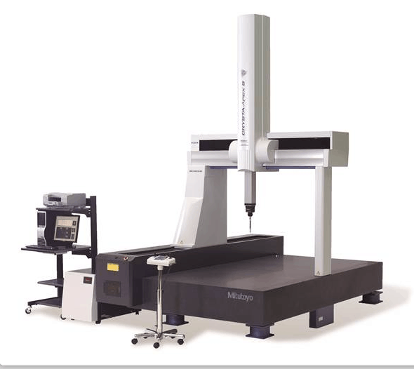
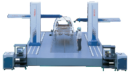
Horizontal arm CMM’s can be huge, and one common application for large machines is automobile body measurement. The photo below shows a pair of horizontal arm CMM’s manufactured by Mitutoyo.
This type of CMM is often fully computer-controlled, allowing them to measure, record, and evaluate data without operator intervention. A joystick for manual operation can control some machines. Accuracy is typically better than an articulating arm CMM, but it suffers somewhat from an inherent lack of rigidity in the cantilevered design.
Bridge
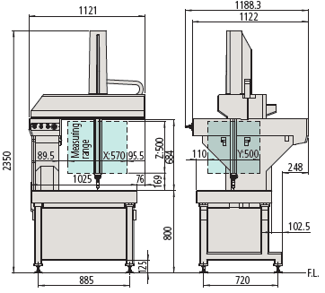
Bridge machines are the most common type of CMM. These machines are typically benchtop or floor-mounted and comprised of a granite measurement table, a “bridge” structure that moves horizontally above the table, a vertical beam that moves along the bridge structure as well as vertically, and a probe mounted to the bottom of the vertical beam via a rotary joint. The bridge traverse movement function is typically driven from one side only and equipped with air bearings to minimize friction.
Bridge CMM’s can be manually controlled or fully automated. The rigid bridge structure makes this the most accurate type of CCM, and temperature compensation is often available.
Cantilever
A cantilever type CMM is similar to a bridge-style machine, but with only one support to allow easier access to the measuring table.
Gantry
The largest CMM’s are gantry type. These machines are mounted on custom foundations and installed in bespoke climate-controlled buildings. The layout is similar to bridge machines. Accessibility and the ability to measure very large parts are the primary advantages of a gantry CMM.
Check out a Bridge/Gantry CMM in action
CMM Operating Principles
Encoders
CMM’s use linear scales (sometimes called linear encoders) to measure translation movements in the X, Y, and Z axes. These scales can operate on a variety of principles, but generally consist of a strip that encodes position information and a sensor that reads the strip. Common types of encoding are optical, magnetic, capacitive, inductive, and eddy current.
Rotary encoders operate on the same principles as linear encoders, and they are used to monitor the angles of articulating joints. From the encoder angle and known member lengths, trigonometry is used to calculate the probe position. Coordinates are adjusted to provide the proper X, Y, Z coordinates for the measurement.
Probes
CMM probes are often touch-triggered, collecting a measurement point every time they touch a surface. A typical probe tip consists of a spherical ruby mounted to the end of a thin stylus. When the probe touches a surface, it transfers pressure through the stylus to a sensor within the probe body, triggering a measurement.
More sophisticated machines have scanning probes that drag across the surface to be measured, collecting measurement points at pre-programmed intervals.
In some cases, contact probes can be replaced with optical scanning probes. These scanning probes use reflections of light to triangulate measurement points on the object’s surface. Recently, advances in technology have allowed optical scanners to increase in accuracy and range. As a result, stand-alone optical scanners are replacing CMM’s for some applications.
Use of CMMs
CMM’s are used for various purposes, including quality inspection, field inspection, creation of drawings for existing equipment, and measurement of worn parts for refurbishment.
CMM’s can quickly and accurately obtain measurements for many geometrical features that would otherwise be very difficult to measure. For example, a CMM could easily check the profile of a surface to determine if a turbine blade is manufactured to the proper curvature. Other properties commonly measured with a CMM include flatness, straightness, circularity, cylindricity, the profile of a line (of a complex curve), concentricity, symmetry, and axial location/orientation.
Operation and programming of coordinate measurement machines are typically conducted by someone who has received specific training for that purpose. Training materials and courses relating to CMM operation are commonly available from the equipment manufacturer. Since CMM operators are often checking the dimensions of a part against a drawing or design, the ability to read technical drawings and knowledge of geometric dimensioning and tolerancing, or GD&T, is essential for these personnel.
Key Take-Aways
- CMM’s measure and record X, Y, Z coordinates for each point measured, creating a 3D point cloud that can be compared to a CAD drawing.
- CMM’s come in many different shapes and sizes with varying levels of accuracy.
- CMM are used to take precise measurements of mechanical parts.
- CMM’s can accurately measure features that would otherwise be very difficult to characterize.
- Proper use of a CMM requires an understanding of GD&T.
For more information on CMM inspection, see:
Part Setup and Datum Qualification Using a CMM
Reporting Size Dimensions with a CMM
The one-page GD&T reference that you will use every day
A visual breakdown of every core GD&T symbol and what it controls, all on one page. Bookmark it. Print it. Actually use it.
Download the Chart