Category: GD&T Symbol Rules and Examples
Articles related to GD&T symbol rules and walk-through examples of GD&T Symbols and their uses

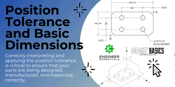
In this video, Brandon compares a Composite Feature Control Frame and a Multiple Single Segment Feature Control Frame to show the effect of each on Position tolerance. What is a Composite Feature Control Frame? A...
The video below is in response to a question that we received on our question line from Ash. The question is as follows: “I regularly see drawings where spacing between a pair of holes is...
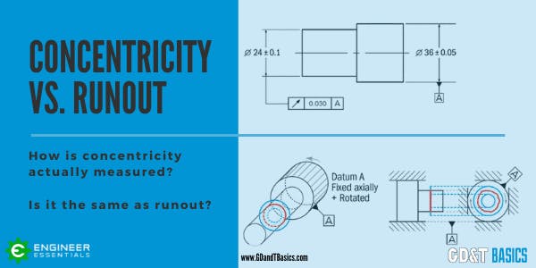
The video below is in response to a question that we received on our question line from Jeff. Jeff asked us if concentricity is always equal to half of the runout value. ASME Y14.5 defines...
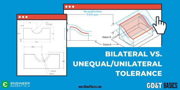
In this article, we explain the differences between bilateral, unilateral, and unequally disposed tolerances. What is a Tolerance? Tolerances on technical drawings communicate the amount of variation permitted from a target dimension. The allowable variation...
In this question line video, Brandon reviews the differences between the GD&T callouts for circularity, circular runout, and total runout. To examine the differences in these concepts it is helpful to first review the Geometric...

Does Runout or Size Control the Circularity/Form Error in GD&T? (Answer: It Depends) In this article video, we aim to answer how Runout is used to control the form/shape/circularity/cylindricity on a cylinder. It also...
Check out this question brought up about Flatness in our GD&T Fundamentals Course. We get a lot of questions about when flatness can be applied and how datums can be used with this. There are...

A datum is theoretical exact plane, axis or point location that GD&T or dimensional tolerances are referenced to. You can think of them as an anchor for the entire part; where the other features are referenced from. A datum feature is usually an important functional feature that needs to be controlled during measurement as well.

Position is one of the most useful and most complex of all the symbols in GD&T. The two methods of using Position discussed on this page will be RFS or Regardless of Feature Size and under a material condition (Maximum Material Condition or Least Material Condition). Position is always used with a feature of size.

The circularity symbol is used to describe how close an object should be to a true circle...

Parallelism is a fairly common symbol that describes a parallel orientation of one referenced feature to a datum surface or line...

The Cylindricity symbol is used to describe how close an object conforms to a true cylinder...

Profile of a surface describes a 3-Dimensional tolerance zone around a surface, usually which is an advanced curve or shape...

Runout is how much one given reference feature or features vary with respect to another datum when the part is rotated 360° around the datum axis.

Concentricity, is a tolerance that controls the central derived median points of the referenced feature, to a datum axis. Concentricity is a very complex feature because it relies on measurements from derived median points as opposed to a surface or feature’s axis.

Perpendicularity is a fairly common symbol that requires the referenced surface or line to be perpendicular or 90° from a datum surface or line...

Total Runout is how much one entire feature or surface varies with respect to a datum when the part is rotated 360° around the datum axis...

Maximum Material Condition (MMC), is a feature of size symbol that describes the condition of a feature or part where the maximum amount of material (volume/size) exists within its dimensional tolerance.
