
ASME recently released the much-awaited Y14.5 2018 GD&T Standard! Find out what has changed from the 2009 edition and what’s you need to know…
The rise of Geometric Dimensioning & Tolerancing has been incredibly phenomenal. A primitive concept in the 1940s, GD&T is now an internationally acclaimed system that has become the industry standard for mechanical part production.
Rather than being marked by radical changes, GD&T has experienced stable growth. Each update to existing rules is made rationally, after collecting feedback from industry members and evaluating the exact pathways to further refinement. In fact, GD&T is perhaps one of the few industries where changes are first reviewed and debated by professionals for years before being fully adopted as common practice.
One such development, and something that is a big deal to GD&T professionals these days, is the 2018 release of the ASME Y14.5 GD&T standard. The Y14.5, published by the American Society of Mechanical Engineering (ASME), is one of the world’s most widely accepted standards for geometric dimensioning and tolerancing.
Like its predecessors, recent ones of which came out in 2009 and 1994, the much-awaited 2018 publication has attracted constructive debate from people curious about the changes made to it and how they contribute to the ever-improving flow of GD&T.
In this article, we identify the major changes from 2009 to 2018 and present our opinion on how they will make GD&T better. In the end, there is a short section on how concerned you should be about integrating it into your procedures.
The Size is Deceptive…
We would like to start with the change that is most obvious. Those who have purchased the digital version of ASME Y14.5 2018 must have received an instant shock upon seeing the number of pages, which have dramatically gone up by more than 100 to 326: the 2009 version was 214 pages long.
There is nothing to worry about though, as this is mainly attributed to structural changes in the document. In previous versions, the information in the standard was organized in a way that the text and the images related to it were presented side by side, on the same page or adjacent pages.
ASME decided to change this by moving all graphical figures and examples to the end of each section. This gives them more freedom in terms of the size of the pictures, which are now bigger and clearer. Moreover, the inclusion of more 3D images (designed using the Model-Based Definition method) makes certain topics more comprehensible than they used to be.
The digital document has direct links to the images wherever they are referenced in the text. This means that if you have the correct PDF reader, you can very easily switch back and forth between text and images.
So even though the initial response to seeing that many pages might be of surprise, it is all for better understanding, with no major conceptual changes added to the GD&T rules.
Concentricity and Symmetry Symbols Removed
This is perhaps the most noticeable change in 2018. Up till 2009, the ASME standard had 14 basic symbols for defining geometric features. Two of these symbols: concentricity and symmetry, have been withdrawn from the toolset.
This change is largely due to the hassles related to using these symbols. To start with, it is always possible to define central features using other, more commonly used symbols. For example, concentricity may have its own symbol, but it is often better defined using controls such as position tolerance and runout.
Speaking in terms of part functionality, only a small proportion of cases actually require the use of these special symbols. It can be argued in these cases that the designer is better off using concentricity/symmetry instead of alternate options. However, this simplification for the designer does not continue down the line on the production side and creates more problems than it solves. Measuring concentricity and symmetry are typically incredibly daunting tasks. This is due to the fact that they require a huge amount of measurements to be taken to be accurate; a median value is determined at multiple points, all of which must fall within the established tolerance zone for the product to pass. A CMM or digital scanner is critical for this measurement, which adds to the cost and time of the inspection process. The digital data file from the CMM takes time to construct and inspect and binds a skilled person who could be used elsewhere. In addition, most machine shops and smaller companies cannot afford such expensive equipment to accurately inspect these features.
Finally, due to the complexity surrounding these symbols, involuntary misuse was also an issue. Designers often wrongly applied them to prints and ended up making people’s work tougher when they were not functionally necessary.
Overall, this change is highly welcomed. By removing these two symbols, ASME has ended a lot of confusion and pushed users towards adapting dedicated usage of Position controls, which is exactly what standards aim for.
Non-Ambiguous Datum Stabilization Protocol
This update is the one most appreciated change among those who inspect parts. It concerns the setting up of a datum using an imperfect feature.
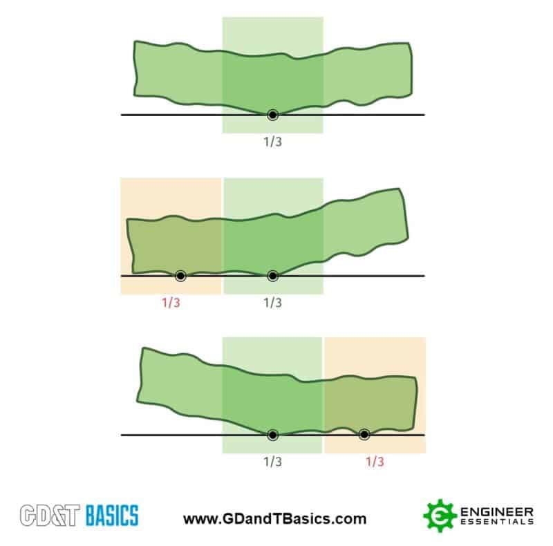
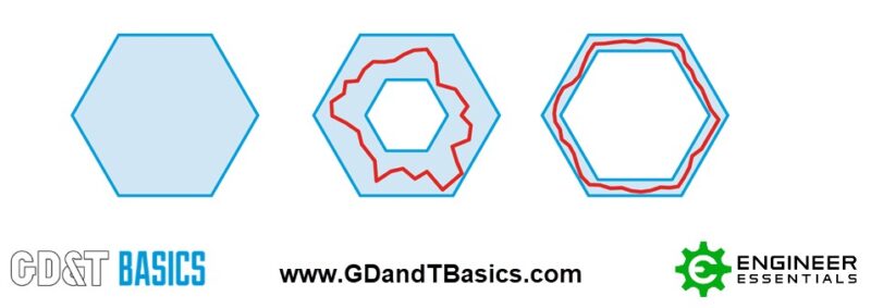
Let’s use a planar datum as an example. Now, if this surface itself is uneven and tends to rock in multiple directions, the inspector first has to determine the exact position which is to be considered as the established datum. This process is known as datum stabilization.
Up till now, the datum stabilization guidelines set out by ASME allowed for several ways to do it. As shown in figure 1 if a planar surface rocks from side to side, there could be a number of acceptable positions that would pass as a datum. This caused great ambiguity as not everyone had the same datum; one person could stabilize it one way and other people some other way.
ASME has tackled this issue by defining one specific datum position (figure 2 below), isolating it from all possible alternatives. The standard dictates:
“The part is to be adjusted to a single solution that minimizes the separation between the feature and the true geometric counterpart”
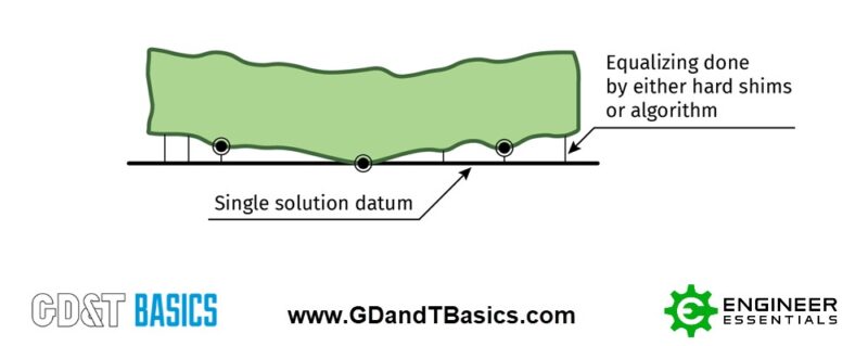
This minimum separation orientation can conveniently be determined using a CMM, if that is what you are using for inspection. This is another positive aspect of this change of rules. Its compatibility with modern technology makes it more likely to be universally accepted and lead to greater standardization of GD&T practices.
Profile All Over
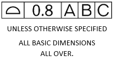
In the 2009 standard, a new “all over” modifier symbol was added to be used with Profile. This allowed profile to be applied all over an entire 3D shape, instead of just being only applied to the profile of the object in that specific view on one single continuous surface only. Per the 1994 version, this could be achieved by placing the words “ALL OVER” underneath the feature control frame. While this concept still exists in the 2018 standard, they are clarifying that a good use for this concept is to place a profile feature control frame in a title block as shown in figure 3.
We are happy to see this as we recommend having a loose, general profile on the drawing to avoid disputes with customers over things such as dents or casting errors (or, god forbid missing dimension).
This will cover your entire part with a loose tolerance that will allow you to reject parts that are out for size, location orientation or form. This is not new, however, it is great that the standard highlights this as a recommended practice.
Dynamic Profile Symbol
The dynamic profile symbol is a very specific addition to the GD&T toolbox. Previously, whenever any feature of size was toleranced, its size and form both shared the same tolerance zone. Although this is often a workable scenario, there was room for improvement.
The dynamic profile symbol basically overrides the default control and targets only the form or shape of the feature. By doing so, the designer is conveying the intention that regardless of the size of the feature, its form has to be confined in its own, separate tolerance zone. This gives a tighter control on the shape, without tightening the size tolerance given to the feature.
This can be seen in figure 4. The complex shape necessitates the use of this symbol, without which the final part can be so distorted it might not be functional.
Continuous Features Clarification
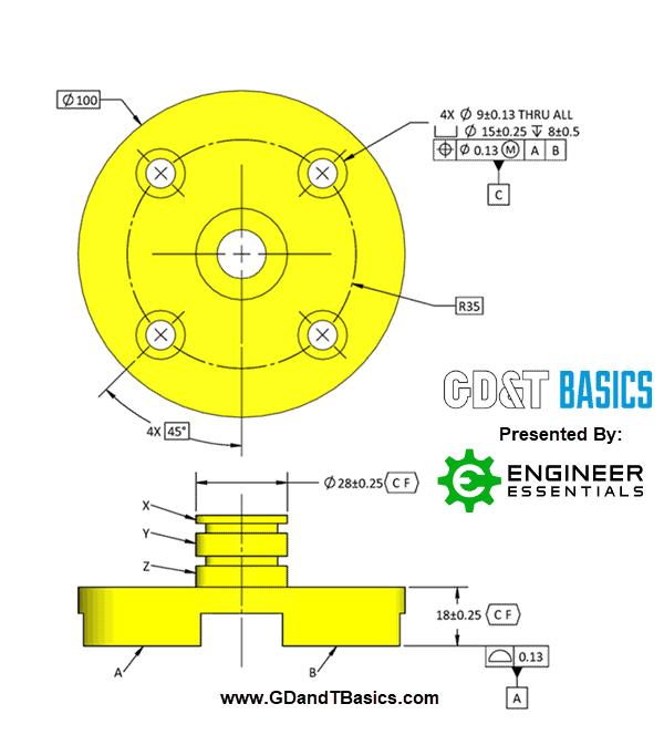
The Continuous Feature symbol was introduced in 2009. This symbol comes in handy when two or more features sharing the exact same size but have a discontinuity or gap that separates them into two separate features. Figure 5 shows a plate with a slot cut into one of its sides. Now faces A and B are practically coplanar but appear as distinct features on an engineering drawing, prompting professionals to treat them as different from one another. To indicate this continuity and save time, the CF symbol is added to their description.
The 2018 standard requires designers to number features that share the same continuity if the continuous feature symbol is NOT used. This is to be done by including nX (n being the number) next to each feature. However, for the continuous feature symbol – the nX is omitted as it is no longer considered a pattern and is used as one feature. You can see this below on the boss that has 3 segments – the 3X is omitted as we are treating the X, Y and Z segments as one continuous feature.
Moreover, ASME has also made it clear that CF can be used for continuous surfaces as well, which was a point of confusion before.
Minor Definition Changes
As in each successive version, the ASME Y14.5 2018 has some minor changes to names and definitions. A summary of some notable ones is given below. It is to be kept in mind that these changes have little to no effect on the interpretation of these concepts. They have been changed though to better clarify when they are to be used.
- Common Datum Features: When a designer establishes a combined datum using multiple pre-set datum, such as “A-B”, it was originally called a “dual datum”. From 2018, this is to be called ‘Common Datum Features’.
- True Geometric Counterpart: This true geometric counterpart is that geometrically perfect body that completely envelopes the part under consideration. It is used to set up a datum for measuring other features. The name ‘True Geometric Counterpart’ has been called back from its origin in the 1994 version, replacing the clearly less impressive ‘Datum Feature Simulator’. There is no difference in the interpretation though.
- Unilateral Symbol: This is a profile modifier that is used to define asymmetric tolerance zones. For example, if instead of ± 1.0, the tolerance zone is + 1.2 / -0.8, the unilateral symbol is used. Up till the 2009 standard, the symbol was used along with phantom lines visually indicating the asymmetricity. The 2018 version specifies a notation that requires only the use of this symbol. We are not the biggest fan of this change as many people are still confused as to which way the Unilateral tolerance zone is to shift. Using the phantom line method from the 1994 version, it was visually clear exactly where the profile tolerance was to be.
The Big Question: Do You Need to Shift to ASME Y14.5 2018?
It is time to address the real issue at hand. Is it really time to update to the 2018 standard? Would it affect your standing if you do not change? What about your customers?
These questions aside, the straightforward answer is probably ‘Not Yet’. As discussed at the start, the GD&T industry is pretty modest with its transitions. The time when this standard is fully incorporated throughout the industry is still far away; an abundance of people are still using the 1994 version.
For more information check out our article on why it may not be the best time to jump onto the new standard quite yet.
Need an Overview of the ASME Y14.5 2009 and 2018 Standard?
Check out our free ASME Y14.5 2009 vs. 2018 Comparison Chart
DOWNLOAD NOW